
Engine & Gearbox
Engine Bearings
Rear Main Oil Leaks 1
Rear Main Oil Leaks 2
Bearing Clearances
Head
Head Stud Lengths
Stuck Head Removal
Head Gaskets
Head Stud Tensions
Sump
Sump Removal – In Vehicle
Magnetic Sump Plug
Misc
Blocked Oil Breather
Clutch Pressure Plate – Locking-Down the Adjustors
Manifold Gasket Repair
Oil Pump – Removal of a Brass Bush
Ring Gear Fitting
Ring Gear Repair
Ring Gear – Preventing Walk-Off
Which Oil to Use – Petroleum vs Synthetic
Gearbox
Defective Transmission Roller Bearing Design
Head Stud Lengths
For members who have assembled a Model A engine, one of the annoying problems is that
sometimes the new or old head studs are not quite long enough to get a full thread into the head nut and you don’t use the full strength of the nut.
I am not sure why this happens but I feel you should screw all head studs into your block until they are tight which seems to cause this shortage of thread protruding. I also put a thread sealant on the threads before installing.
I suggest you order the longer stud (part Number A-6066-C). The regular short stud is 3 15/32 of an inch long but A-6066-C is 3 ¾ inches long. You would probably need 14 of these. The stud between number 3 and 4 spark plugs will be longer if you use an ignition conduit clip.
The good book says the short head studs should protrude 2 ¾ of an inch above the actual blocks top surface. The ultimate aim is to have the stud thread protruding two threads above the nut when torqued!
I suggest you measure the height of one installed stud once tight in the block before you go to the trouble of ordering your engine parts. If it is shorter than 2 ¾ of an inch you should order the slightly longer studs mentioned above.
Alan Jeffree, Western Model A News, April 2013
Top of page
Removal of a brass bush from a Model A Oil Pump
The first task is to remove one of the two bushes without damaging the body. You can’t drive the bush right through the pump as there is a step machined into the body where the bush sits.
There are two different size bushes use in Model A oil pumps. All of the pumps I have rebuilt have had a half inch bush. My instructions here apply to this size. The slightly larger bush used on some Model A oil pumps would just need a different size tap and bolt. A metric tap, and bolt could possibly be used rather than NF.
Removing a bush
Use a 9/16th NF (taper) tap to make a thread inside the brass bush, most of the total bush depth. Then screw a 9/16th NF bolt into to bush at least half way into the thread. Next use a longish rod and a hammer to drive the bush/bolt out. It usually drives out without too much effort. The second bush can be removed by repeating the above.
Hans Hurij, Western Model A News, April 2014
Top of page
Rear Mail Oil Leaks 1
Does your Model A leave oil on the driveway? One of the biggest problems with the Model A Ford was, and still is, the persistent main bearing oil leak. But there is a solution to the problem. You can stop that oil leak by following all the steps outlined here; but do not skip any or you will be wasting your time.
A little background on the engine will prove informative and show why the problem with the rear main exists. The flywheel in the Model A weighs several times that of flywheels in modern cars. Thus dips, hard bumps, sudden stops and quick starts throw a tremendous
amount of weight of the rear main. Sudden starts and stops tend to slam the flywheel backward and forward against the bearing thrusts. As they get looser, the harder the pounding. This can continue until the vibration and pounding breaks up the babbitt and then the bearing is gone. When this happens there is only one recourse and that is to have them repoured and align-bored. A close inspection will determine the condition of the main bearing.
At this point it will be necessary to have the crankshaft “miked” (measured with a micrometer) to determine if it is flat – that is, out-of-round. The center main will be worn more than the other two, normally. This is also the first bearing to go under hard driving conditions. The reason for this is the heat is greatest at the center of the engine and the babbitt tends to soften there first, plus the fact the center main has to help hold the pressure each time the engine fires for all cylinders.
Assuming that the babbitt bearings are sound and the crankshaft is within acceptable tolerance, we can turn our attention to tightening the main bearings.
- Make sure the aluminum seal in the block is tight and a seal between it and the block is made. Permatex gasket cement will do the job fine. The reason for this is, oil can “blow by” this seal if it is loose in the block.
- Place the crankshaft back in the block. End play of the shaft should be between .002 and .004 of an inch. The Ford Service Bulletin for February 1928 states .004 to .007 of an inch. However this is more than actually required. If more than this is encountered, a good re-babbitter can build up the old bearing thrusts at reasonable cost. Remember also that too much end play in a crankshaft lets the shaft act as an oil pump as it moves back and forth. Back pressure in the crankcase helps move the oil out but not in.
- Start with the rear main first. Because this is our area of trouble we will be extra careful here as to its proper fit. Place the two rear main bolts in the block. Next place the shims (equal amount on each side) over the bolts. Inspect carefully to see that the front and rear section of the shims touch the crankshaft simultaneously. If the shim rocks, this will create a hole at the rear of the main, and you must file or cut out around the outer side of the bolt hole to allow the shim to move in and touch the shaft. You will notice that at the front and back of the shim there is a bulb-type end. This will match the “closed” section of the back and front part of the rear main. This is designed to hold oil in the main and lubricate the shaft. Under no condition should shims be used that have been modified to allow tightening of the rear main without removal of the cap. This allows oil to seep out by the bolt into the flywheel housing.
- Inspect the rear bearing cap to make sure it has the large oil return tube without ball check. Make sure all dirt and carbon is removed from the tube as well as the trough at the bottom of the bearing. Do not alter the tube or bearing cap in any way. Tighten the rear bearing to .001 clearance. Plasti-gage (see note in Bearing Clearances) is available at most auto parts stores to indicate when the bearing is tight. The crankshaft can be turned by hand at this setting by gripping the throws and turning. Remember also, you can have a tight crank and still not have a good seal unless the bearing fits to .001 all the way around the shaft. A simple home test is to use machinist’s blue dye. Also keep in mind that if the engine is in poor condition and you are experiencing a lot of blow-by, the trough and open return tube tend to let pressure blow oil out the back main. The only cure for this is complete rebuilding of the engine. Incidentally, on a new rebuilt engine, you will get some blow-by until the rings have seated. Some restorers have had good success with the moulded seal now being manufactured and available from most parts houses. No modification is required of the engine. The only thing to watch here is to be extremely careful to see that none of this seal mashes out between
the block and the bearing cap. Do not starve the rear main by closing off the oil line leading to the main. This definitely is not recommended as oil to the mains is gravity fed and this is the reason the centre main goes first, because a big enough volume of oil cannot move through it. The oil not only lubricates but cools the bearing. There is only one hole for the oil to reach the rear mains. There are no others leaving them. - Now loosen the rear main nuts one full turn and tighten the centre main using the same procedure. Of course on the front two mains you do not have to worry about the placement of shims against the crankshaft.
- Loosen the centre main nuts one full turn and tighten the front main. After fitting up the front main, go back and retighten the other two key nuts and the job is complete.
- Now with all connecting rods installed, our next critical oil leak area is at the rear of the pan. Normally the thick cork gasket across the back of the rear main is too long. Simply cut it off where both ends touch the block until there is no bulge in the middle. Install the pan using sealers.
- Another area of oil leak is at the front crank pulley. If the pulley is loose on the shaft, two things can happen. Oil will flow out between the shaft and the inner wall of the pulley. The loose pulley will also bore out a new seal fast. The original pulley was very snug on the crankshaft. If you still have the original pulley and a groove is worn in it at the seal area, it would be better to have it built up with brass and then machined, than to buy a reproduction. Now you can take that Model A out on the road and enjoy it
more. And after your trip you will be returning to the cleanest driveway in town.
Checklist
- Tight upper seal in block
- Good bearing surface on mains
- No end play in crankshaft over .007
- Shims moved over tight against crankshaft
- Clean trough and return tube
- Clean breather pipe
- Tight fitting front pulley
by Verle Smith
We have had so many questions on oil leakage that we
have decided to reprint this excellent article from
the March-April 1968 issue of The Restorer
From How to Restorer your Model A Volume 7, to
assist club members in need of the information.
Pat Bussard, Western Model A News, Nov 2010
Rear Main Oil Leaks 2

Western Model A News, Feb 2016
Top of page
Bearing Clearances
This was a tip given to me by a long time Model A Club member and mechanic, Steve Read.
If you want to check the main or conrod bearings for clearance in a Model A, the following is an easy method once your motor is open. These bearing should all have between one and one and a half thou clearance.
With a cap off, find a piece of “invoice” paper about the size of a five cent coin (the shape isn’t critical) and place this in the bottom of the wiped cap and replace the cap, bolting it up tight then try moving it by hand. If the gap is OK the rod or crankshaft, whichever you are checking, should not move.
Invoice paper is about 2 thou in thickness. You must not use anything thicker or this exercise is pointless! Check with a micrometer if in doubt. As an example, Reflex copy paper is 4 thou.
Word of warning! Do one bearing at a time to avoid any mixing up! It is absolutely critical that the shims already in the cap must stay on the exact side you find them! If they are separated, take care not to drop any. I was given another valuable tip by my friend and sponsor, Ray Abbott, to mark each shim side with a different coloured texta pen.
If you find the 2 thou invoice paper doesn’t lock the bearing, to correct the clearances is another story.
![]()
Connecting rod showing the coloured texta to mark the shims. The other side would be a different colour. Mark the rod and the shims so you can replace them on the same/correct side.
Flexigauge/Plastigage. Inside the packet is a very thin thread of special plastic which squashes when you place it under the cap. The edge of the packet (that looks like a piano keyboard) is then used to compare the width of the squashed plastic to get a thou reading of the gap. You don’t try turning the conrods when using this product.
Flexi Gauge does come in three colours to measure different size clearances. I find green the one appropriate for Model A work.
You can’t use Plastigage to check the clearances in the main bearings with the motor in the vehicle. This is because when you remove one main bearing caps the crankshaft will sag downwards a little with gravity. The Plastigage will squash as you push the crankshaft back up as you tighten the main bearing bolts and give you a false reading. The use of 2 thou paper to check whether crank will turn by hands is okay! Steve Read and Ray Mahony (both qualified mechanics), have both contacted me with this additional information.
Alan Jeffree, Western Model A News, July 2014
Top of page
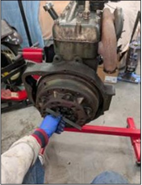
Stuck Head Removal
If you are trying to remove your Model A head and it is stuck – simply remove all head nuts (if you have not already done so). Take out all of the spark plugs and using your hand crank, turn the engine over until pistons #2 and #3 are at top dead centre. (A torch will aid in looking in the #2 and #3 plug holes.) Take two pieces of 3/8” nylon or cotton rope, several feet long and feed one end of each rope into the #1 and #4 cylinders through the plug holes. Then simply hand crank to compress the rope and with a little force on the crank, the head will lift right up. Try to use about the same length of rope in each cylinder so as to lift the head evenly.

Western Model A News, October 2019 (re-published from the Script A news)
Head Gaskets
Replacement Model A head gaskets may be marked to indicate which side goes upwards. If not always install a new head gasket with the crimp side up. The reason for this is that over years of running, the gasket crimp will wear its way into the contacting surface. It is easier to remove the worn area in the head than to resurface the block.

John Moorehead, Western Model A News, April/May 2014 ?
Head Stud Tensions
Members should check head stud tensions at least once a year on their Model A. There is a
correct sequence to follow which is shown in many Model A books. Basically you start in the centre of the head and alternate outwards in a snail trail to each outer end.
Remove one nut at a time, starting in the middle of the head, clean the thread and place a
coating of oil on the stud then tension that nut to 50 ft lbs (55 lbs if a high compression head).
Working alternately outwards following the correct sequence from the centre, do each nut one at a time. When complete, recheck all nut tensions in the correct sequence.
John Watson, Western Model A News, March 2012
Top of page
Blocked Oil Breather
The perennial Model A Ford problem of the rear oil main leaking has been the subject of many articles.
If the major cause due to excessive clearance with the rear main bearing has been rectified then the following inspection may be of assistance.
The Model A engine is short on breathing air. This is why Ford increased the size of the breather (oil filler) pipe in 1932 on the B engine. Reduced breathing of the engine adds to the pressure in the bottom of the engine and hence aggravates the problem of oil leaks.
In 1928 the design of the filler pipe was changed so that the baffles pointed down instead of up to block oil mist in the crankcase. Also the baffles in the filler cap should not be flattened or distorted and hence add to the crankcase pressure. This is a common problem which is often overlooked.
Another test is to hold a plastic bag around the filler pipe with the cap removed. Run the engine at a fast idle and bag should flutter. If it does not and fills up with air there is excessive blow- by in the crankcase. This can be caused by worn rings or valve guides.
Excessive pressure in the crankcase and restricted breathing will add to the problem of oil leaks.
John Moorehead, Western Model A News, May 2018
Top of page
Sump Removal – In Vehicle
If it is necessary to remove and refit the oil pan (sump) whilst the engine is in the vehicle and you are on your back under the vehicle the following simple tools will assist.
The first is an oil pump temporary retainer. This device consists of 1/8th inch plug with a centre bolt. After removing the plug or oil fitting in the block the retainer is screwed into the hole and the centre bolt tightened just sufficiently to hold the oil pump in position when the pan is removed. Do not over tighten the securing bolt. This oil pump retainer is stocked by Henry’s Ford T and A Parts and other USA suppliers. (part number
A6621R)
The second aid is a set of four guide pins. Make these from four 5/16th inch 18 TPI (UNC) bolts. Using a hacksaw cut four pins about 1 and 1/8 inch long with approximately 1/2 inch thread on one end. Bevel the unthreaded end a little and cut a slot in the end for a screw driver. When the sump is ready to replace, position the four guide bolts we have just mentioned into the block, two on each side to guide the sump and hold it steady in place. The pan bolts can now be easily inserted. Finally remove the four guide pins using a screw
driver and insert the last four pan bolts.
Don’t forget to then remove the oil pump retainer and refit the original plug or pressure gauge fittings.
John Moorehead, Western Model A News, Sept 2013
Magnetic Sump Plug
Want to trap, collect, and hold iron and steel chips and filings in your crankcase? Well, I do, but in a convenient location.
Remove the drain plug (make sure you have a pan under it to catch the oil) from the oil pan and clean it thoroughly of any oil and dirt. Select a small cylindrical magnet, from one of those give-away screwdrivers and set it into the plug.
I use a quick setting 5-minute epoxy to secure the magnet in place. That’s all there is to it! You will be surprised to see all the material collected on the magnet after your next oil change. It won’t collect babbitt or brass, but sure gets the abrasive ferrous material that can harm your engine.
News-A-Letter, Heart of America A’s, Western Model A News, May 2020
Manifold Gasket Repair
I recently made an interesting repair to a failed exhaust manifold gasket. We were on an extended trip (4,500 miles) from San Diego to the deep woods of Vancouver Island, BC when the gasket blew out. The primary cause of the failure was the warping of the manifold. We didn’t have a replacement gasket so we cut gaskets from regular higher temperature stock. As we knew would be the case, the misalignment of the exhaust manifold with the engine block did not allow gland rings to be fitted, but in this particular circumstance we needed something to augment what was obviously an inadequate seal.
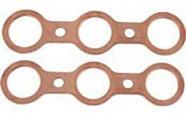
The trick we used was to make exhaust manifold gland rings from copper water pipe. We cut with a hacksaw, as carefully as we could, lengths from the pipe that would extend out of the engine block just the thickness of the gasket material. These rings were split and the joint hand filed until they could be tapped firmly into the engine block counter bore. Our reasoning was that when the manifold assembly was tightened into place the gasket would be compressed somewhat and the interference of the misaligned manifold faces with the copper glands would fix them into place and provide exhaust gas barriers for the vulnerable gasket material.
There was no failure of the gasket after the rings were installed. Other antique automobile engines I am familiar with do have these exhaust manifold sealing rings and they make an almost foolproof manifold seal in conjunction with a gasket. Ford had a terrible problem with warping of the manifold and had to abandon the gland ring in production. Our experience in the North Woods with this copper ring approach suggests that the seal can be greatly enhanced. It directs the hot exhaust flame away from the gasket seal and is held firmly in place.
Subsequently we have machined the manifold assembly gasket face flat, and have installed copper glands just because it is so easy to do, and as was demonstrated to us, is effective even without the ring penetrating the manifold counter bore.
Richard Bates, San Diego, California, as appeared in Ford Torque (MAFC of Vic), March 2020
Ring Gear Fitting
A quick, easy way to install a flywheel starter ring instead of using a torch is as follows: CAUTION: Do this outdoors and it works just as well in a barbeque pit or stand. Place the ring on the cardboard carton it came in or a pile of cardboard. In the centre of the ring pour some charcoal lighter fluid or some flammable solvent and ignite it. Be ready, when the box is just ashes and hot coals, remove the ring with pliers and sit it on the flywheel.
Another word of caution – make sure you have the ring facing the correct direction. It usually falls all the way on for me.
Dexter L. Blether, Longview, Texas, MAFCA On The Road via Ford Torque and Western Model A News, Feb 2022
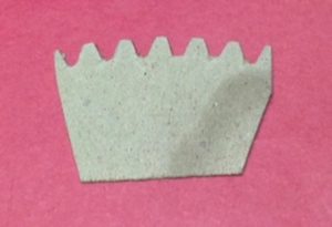
Ring Gear Repair
The other day when cleaning my workshop, I came across a memory. Many years ago when I rebuilt my engine for the first time, I noticed that the ring gear showed some significant signs of wear. Model ‘A’ engines when shut off usually come to rest in one of two positions and this was evident by the wear on my ring gear. This repair was done before digital cameras so I don’t have any pictures of the ring gear – so you will just have to imagine what it looked like.
Being frugal and not having a lot of cash at that time, I decided to repair the ring gear rather than buy a new one. First, I punched witness marks on the ring gear and the flywheel to act as reference points when putting the ring gear back on the flywheel. I used a drift and hammer to slowly work the ring gear off the flywheel. Using the good portion of the ring gear, I made up a template of the gear profile, see the photo below. Using my oxy/acetylene torch, I built up each of the worn gear teeth with braze. Next using my template and a file, I filed each tooth profile to match the template and followed the angle and shape of the teeth that were in good condition.
Now the next part that I still get some complaints from my wife about. Using our oven, (make sure your wife is not home as they are somewhat protective of the stove), I placed my ring gear in the oven at 350 deg. F for about 20 minutes. That will ensure a nice even heat and expansion of the ring gear. Next with the flywheel on the floor in the kitchen (make sure it is clean or you will get more complaints about grease on the floor), remove the ring gear from the oven and position the witness marks at 90 degrees from the original position. That way the starter will be engaging the original teeth and only pass over the repaired teeth while starting the car. I actually had time to make sure the gear was positioned correctly and firmly against the flywheel edge before it cooled and locked onto the flywheel.
Now the most important step! Open all the doors and windows to air out the house. I failed to do this step and was busted by my wife as soon as she stepped in the door. It seems women have very good sniffers when you are up to no good. In future I will have to put an old stove in my workshop if I have to repeat this repair. Fortunately the repair I did has worked for many years now.
John Wyld, Quill & Quail, Feb 2021 and Western Model A News, March 2023
Ring Gear Walk-Off
A not uncommon occurrence in the modem era is for the starter ring gear on the flywheel of a Model A to want to attempt to walk off its mounting position. The ring gear is an interference press fit on the flywheel and in the old days that seemed to be enough to keep it in place. It may be that the repo ring gears are not made correctly. That would be no great surprise.
The ring gear is pressed on from the front of the flywheel until it sits flush against a machined stop. The gear on the end of the starter sits behind the ring gear. When the starter is engaged the starter gear is actually attempting to pull the ring gear forward and away from the machined stop. This can cause it to move forward if the press fit is not tight enough. It would have been better if Henry had mounted the ring gear from the rear of the flywheel against a machined stop.
I had the experience of one coming loose. It walked forward almost an eighth of an inch. When I would start the car up I would hear a knocking sound for about 30 seconds, then the noise would disappear. What was happening was the ring gear was hitting the ends of two of the starter mounting bolts that protrude very slightly through the clutch housing. This occurred because the starter gear jerked the ring gear forward. After about 30 seconds of rubbing the ends of the bolts the ring gear would be knocked back enough to clear the ends of the bolts and the noise would stop.
The out-of-position ring gear can also cause the starter gear to jam against the ring gear. This also happened to me and that was how I discovered the ring gear was walking. I was able to tap the ring gear back into place by rotating the engine and tapping the gear with a brass drift every few inches through the starter mounting boss. This is only a temporary repair, as the ring gear will continue its walk about, and it certainly did.
I finally pulled the engine and flywheel. I could see witness marks on the ends of two of the starter mounting bolts where it had worn the ends smooth.
There is a permanent fix. A machine shop can press the ring gear back into place then pin it with setscrews. Holes are drilled and tapped though the surface of the ring gear and into the flywheel in three equally distant places and seated with lock tight. This would be a prudent thing to have done anytime you are having a new repo ring gear installed.
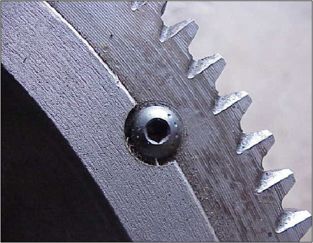
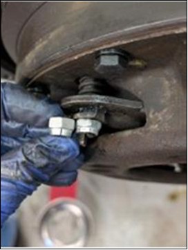
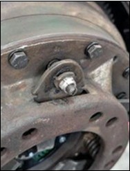
The setscrews lock the ring gear to the flywheel

Three setscrews are installed at 120 degrees distance from each other
Tom Endy (from Ford Torque, June 2025), as appeared in Western Model A News, September 2025
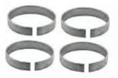
Defective Transmission Roller Bearing Design
The two Model A roller bearings on the market today, part numbers A-7118 and A-7121, have a short service life due to the change in design.
The bearings that were on the market a few years ago were of a different design, (but carried the same part number), had an axle at the end of each roller element that protruded through holes drilled into the end caps.
The current design has a series of mushrooms stamped into the end caps; the roller elements have holes drilled into both ends of the roller elements that rides on the mushrooms. The photo below shows a disassembled new roller bearing of the current design on the market. Note that the holes in the end of the roller element do not appear to be symmetrical. The bearing has a total of 12 roller elements and four support beams. The four support beams were cut in order to disassemble the bearing. The one single roller element is simply standing on-end over a mushroom. Once the roller element wears into the mushroom on the end cap, the roller element will become uncaged and the bearing will fail. Most have failed between 300 and one thousand miles.
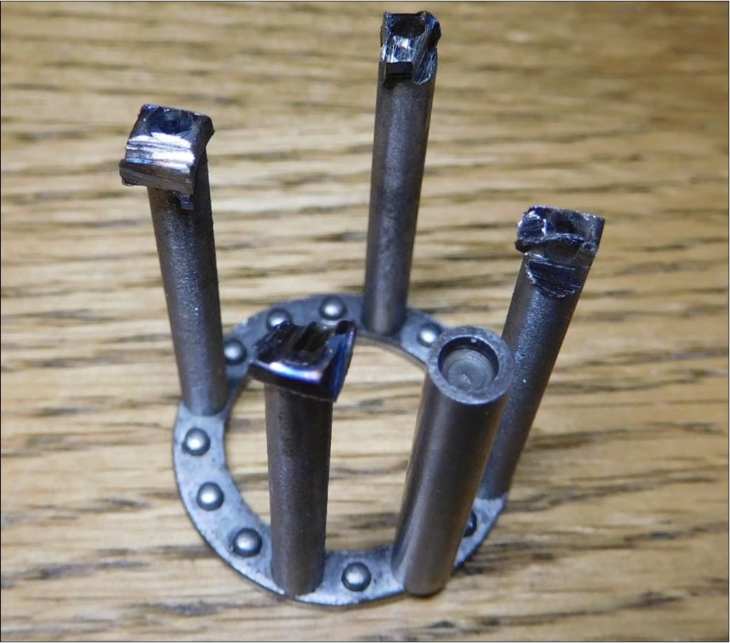
Tom Endy from Ford Torque Jan-Feb 2025 and Western Model A News, March 2025
Clutch Pressure Plate – Locking-Down the Adjustors
Doing a clutch job on a Model A is a true “adventure”—and by adventure, I mean you’re either pulling the engine or the rear end. Neither is a quick afternoon task. When you finally get that clutch replaced, you want the peace of mind that you won’t have to see the inside of that bell housing again for a long, long time.
The Solution: Flex-Top expanding nuts.
A critical step in any clutch job is adjusting the pressure plate fingers. The trick is ensuring each finger is exactly the same depth from the surface of the pressure plate collar. The specification is tight: no more than 0.002” difference. If they are uneven, the throw-out bearing will engage the fingers at different times, causing the clutch to engage unevenly against the flywheel. This results in dreaded clutch “shudder.” We all want that silky-smooth engagement that makes the Model A pleasurable to drive.
The problem with traditional lock nuts once you’ve dialled in that perfect adjustment, you need to ensure those nuts stay put. The original design used distorted-thread lock nuts. These work by having the threads punched in two places to create a friction fit. The downside – they are essentially one time use. Once you remove them, the threads reform, and they begin to behave like a regular nut—making them prone to backing off due to vibration.
For my builds, I prefer Flex-Top locking nuts. These work on a similar principle to distorted threads, but with a clever engineering twist: the top of the nut is sectioned and tilted inward. This creates a spring-like grip on the bolt that doesn’t damage the threads. Therefore, they are reusable*. I recommend the “thin” (low profile) version as the flex top sits lower on the screw, gripping securely below the screwdriver cutout where the screw itself is more rigid.
You might be tempted to use Nylocks, but don’t. Nylon inserts typically soften around 120°C. On a hot summer day after a long cruise, your clutch housing can approach those temperatures, risking a failure.
Specs: 5/16″-24, Thin Profile.
It’s a small investment for the “set and forget” confidence every Model A owner deserves!
* – Even flex-top locknuts will need to be replaced after a few uses, but probably not within the ownership life of a typical Model A hobbyist.
Tim Diehn, from NIMAFC May 2026, as appeared in the Western Model A News, June 2026