
Electrical
Cut-out Operation
The Electrical System Pt.1
The Electrical System Pt.2
The Electrical System Pt.3
The Electrical System Pt.4
The Electrical System Pt.5
The Electrical System Pt.6
Dashboard Lamp
Distributor Shaft Lubrication
Fuse Installation
Fuse Block Terminal Shorts
Handy Bypass Wire
Headlight Grounding
Horn Maintenance
Horn Problems and Remedies
Horn Rod Clip Tool
Ignition Cam Screw
Ignition Misfires
Ignition Switch Lubrication
Ignition System Operation
Installing 6V LED Lights
Isolating an Electrical Fault
LED Headlight Flickering
Modern Condensers
Points
Reading the Ammeter
Rotor Spark Gaps
Simplified Model A Electrical Drawing
Spark Advance
Terminal Box
Terminal Box Overheating
Volt Drop Testing
The Electrical System Pt.1
During a number of conversations and discussions over the years, it is apparent that the area of our Model A that is least understood by many members is the Electrical System. So I thought I might write a number of articles to explain, without getting too deep into the technical side of things, what goes on in electrical systems. However, some basic knowledge of the structure of matter, magnetism and electrical theory is needed to follow the operation of components and systems. Let’s start with:
THE STRUCTURE OF MATTER
All matter is made up of atoms, which in turn, consist of electrons, protons and neutrons. Electrons have a negative (-ve) electrical charge, protons have a positive (+ve) electrical charge and neutrons have no electrical charge and therefore have no part to play in electrical theory.
Neutrons are located with the protons in the centre or nucleus of the atom.
Electrons rotate around the protons in a number of orbits similar to our solar system. The simplest of all atoms is the hydrogen atom, which has only one electron and one proton. Copper (most commonly used as a conductor in our systems) has 29 electrons rotating in four orbits around 29 protons.

The electrons in orbit are attracted to the protons in a similar way to our planets being attracted to the sun. The intensity of the attraction determines whether the material is a conductor or an insulator. The electrons in the outer orbit of copper atoms are very loosely attracted and can be easily pushed away from the atom, therefore, copper is a good conductor.
The electrons in an insulator, such as porcelain used in spark plugs or plastic surrounding wires, are very tightly bound to the protons so cannot be easily be forced to leave the atom. When a force is applied to the atoms of a conductor, electrons move along the conductor from one atom to another throughout the length of the conductor. When this happens we have what is called an electron flow or ELECTRICAL CURRENT which is measured in Amps. The force that caused the movement is VOLTAGE which is measured in Volts.
The RESISTANCE to the movement of electrons in the conductor is measured in Ohms. The resistance of a conductor will depend on the material from which it is made, the cross sectional area (thickness), and length of the conductor. If you increase the thickness, you decrease the resistance, and if you increase the length you increase the resistance.
There is a direct relationship that exists between these three factors. Technically it is stated in Ohm’s Law as:
“THE CURRENT FLOWING IN AN ELECTRICAL CIRCUIT IS DIRECTLY PROPORTIONAL TO THE VOLTAGE, AND INVERSELY PROPORTIONAL TO THE RESISTANCE.”
In simple terms, this means that if you increase or decrease the voltage (force –volts) then the current (amps) will increase or decrease at the same rate.
If you increase the resistance (Ohms) you decrease the current (amps) at the same rate, or if you decrease the resistance you increase the current at the same rate.
It can be important to remember this when trying to work out why electrical components sometimes don’t work as they should. I will expand on this in a later article.
Ray Mahony, Western Model A News, Dec/Jan 2014/15
Top of page
The Electrical System Pt.2
MAGNETISM
Following on from last month you will remember that the three main aspects of electricity, that we are concerned with, are: voltage (pressure), current (flow) and resistance to flow. If you think about it for a while you may see that these aspects are similar to a hydraulic system. More about that another time.
Although we are unable to see electricity we can see the effect of it. You have no doubt seen the heating effect; the filament of a light bulb glows white hot to give off light, the spark from a spark plug is hot enough to ignite the fuel mixture in the cylinder.
You have experienced the chemical effect of electricity which changes the chemical composition of the battery fluid when charging the battery. Also corrosion of aluminium components in the modern cooling system is caused by chemical reaction within the system.
Another effect, which is our subject this month, is the MAGNETIC EFFECT. I have no doubt that all of you would have played with ordinary old magnets (permanent magnet) sometime during your life. You will know that magnets are attracted to metals

Magnets have an invisible force field that surrounds them that flows from a NORTH pole to a SOUTH pole through the air.
Like poles repel – unlike poles attract. That is if you place magnets end to end they will either attract each other or push away from each other.


Electro-magnets act in the same way. But what is an electro-magnet? If an electrical current passes through a conductor, a magnetic field is produced around that conductor. The direction of the magnetic field is determined by the direction of the current.


Shape and direction of magnetic field around if the direction of current flow is reversed, a conductor magnetic field will be reversed.
If the conductor is wound to form a coil, the magnetic field from each winding will work together to produce a magnet similar to a permanent magnet.

Magnetic field development around conductors set side side (as in a coil). Magnetic lines of force will not cross, but run together
Magnetic field development around conductors set side side (as in a coil). Magnetic lines of force will not cross, but run together.
The strength of an electro-magnet is determined by the number of turns, the amount of current flow and type of core, or what is inside the winding. If a piece of soft iron is placed inside the winding, the strength of the magnet will be increased by about 1000 times.

Section view of windings around an iron bar, showing the development of a field around a coil
Ray Mahony, Western Model A News, Feb/March 2015
Top of page
The Electrical System Pt.3
MAGNETISM (continued)
The polarity of an electro-magnet is determined by the direction of the winding and the direction of the current flow. If you change the direction of the winding, the polarity will change and if you change the direction of the current flow, the polarity will change. If you change both at the same time, then the polarity will be the same as before.

Multiple magnets can be used to either increase or decrease the overall strength of the magnet. The strength of an electro-magnet fields is stated as the ampere-turn value; ie. the number of turns in the winding multiplied by the current flowing.

Ray Mahony, Western Model A News, Mar/Apr 2015
Top of page
The Electrical System Pt.4
WATER ANALOGY
Before looking at how electro-magnetism is used it is probably a good idea to get a picture in our mind’s eye as to how current flows and is effected in an electrical circuit. In many ways an electrical circuit is similar to a hydraulic circuit.
The hydraulic circuit has a pump that provides the pressure, a control device (tap) and a component to operate, (e.g. a hydraulic motor) and pipes to carry the fluid to the component and back to the reservoir. The system could be fitted with a pressure relief valve, pressure gauge and a flow meter.

The electrical circuit has a device to provide a voltage (pressure) i.e. the (battery, generator or alternator), a control device (switch), a component to be operated (e.g. relay, cut-out, starter motor or headlight) and wires to carry the current from the voltage source to the component and back to the power source.
The pressure in the electrical circuit is measured by a volt meter, flow is measured with an ammeter and the pressure relief, on vehicles other than a Model A, is controlled by a voltage regulator.

It is probably worth noting here that you can have a voltage being applied to a circuit without having current low. If the electrical switch is off there is still voltage being applied from the power source. Just as if you turn off the nozzle on the end of your garden hose there is still pressure in the hose.
If you have trouble imagining current in the wires of an electrical circuit, just think of it as water flowing through pipes.
APPLICATION OF ELECTRO-MAGNETICS
We now have enough technical knowledge to look at how some of the electrical components in our car work. Electro-magnets are used in generators, starters, wiper motors, cut-outs, horn and light relays and ignition systems.
We will start with a cut-out relay or perhaps as it should be more correctly called a reverse current relay.
The cut-out allows current to flow from the generator to the battery and other circuits when the generator is charging. That is when the generator output voltage is higher than the battery voltage. It prevents current flowing back into the generator when the generator voltage drops below the battery voltage. Current flowing from the battery to the generator would over heat the generator winding and burn them out.
Ray Mahony, Western Model A News, Apr/May 2015
Top of page
The Electrical System Pt.5
CUT‐OUT OPERATION.
Let’s start with the construction of a simple relay. The relay consists of a winging around a soft iron core, a spring loaded soft iron bar (armature) and a set of contacts. If a current is passed through the winding a magnetic field is produced that pulls the armature down to close the contacts. With the contacts closed a second circuit is available for current flow.

The cut‐out or reverse current relay has two windings. The first is of very fine wire and carries only a small amount of current, this is known as voltage coil. The second winding is made of much thicker wire and carries the main current to the battery and other circuits. It called is the current coil.
The relay has two terminals; one connected to the battery and the other to the generator. The current coil connects between the generator and the moving contact. The voltage coil is basically an off-shoot from the current coil and connects to the frame of the relay (earth).

Initially the contacts are open, so any current from the generator flows through the current coil and then through the voltage coil the earth to produce a magnetic field. You will notice that the direction of current shown in the diagram is the same in both coils so their magnetic fields assist each other. When the generator voltage is high enough the magnetic field will pull the armature down and close the contacts. Current can now also flow through the closed contacts to the battery.

The voltage at which the contacts close can be adjusted by bending the spring mounting slightly to alter the tension on the spring. To check this, place a voltmeter between the generator terminal and earth. Run the engine and note the voltage reading when the contacts close.
CAUTION: The contacts should never be closed when the generator is not charging. Doing so will create a short circuit and serious damage will occur.
When the generator stops charging, that is the battery voltage is higher than the generator voltage, current will flow from the battery through the closed contacts and both winding. Now you will notice that the current is flowing in opposite direction through the current coil, but in the original direction in the voltage coil. The magnetic fields set up by the coils are opposite to one another. They cancel each other out and the spring opens the contacts
So we have an electrically operated switch that connects the generator to the battery for charging and dis‐ connects the battery from the generator when the generator is not charging, and so protecting the battery from unwanted discharge and the generator from burn‐out.
TESTING
If you find an old cut‐out and want to know if it will work or not the test is fairly simple.
Assuming the cut‐out is removed from a vehicle:
- Remove the cover and have a good look at the components. Make sure the contacts are reasonably clean and they open and close alright. Check the winding for general condition if they don’t look too ratty they will most likely be ok.
- Using an ohmmeter or continuity tester place one terminal of the tester on the generator terminal and the other on the frame. You should have a complete circuit.
- Connect the test across the two terminals. There should not be a circuit.
- With the tester still connected across the terminals close the contacts. You should get a complete circuit.
- For the final test, connect a battery across the generator terminal and the frame. You should notice the contacts close Just be aware that the terminals I am referring to are the generator and battery terminals on the cut‐out. If you find you are unable to trust this electrically operated mechanical switch, which has operated very successful y for many years, you can replace it with a modern electronic device called a diode.
Ray Mahony, Western Model A News, June/July 2015
Top of page
The Electrical System Pt.6
ELECTRO-MAGNETIC INDUCTION and THE IGNITION SYSTEM
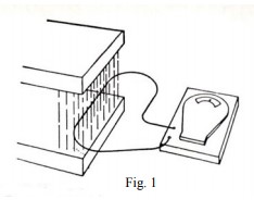
“ELECTRO-MAGNETIC INDUCTION” is the process of producing a voltage through the interaction of a conductor and a magnetic field. This process is used in the ignition coil and the generator.
If you pass a conductor through a magnetic field, or pass a magnetic field over a conductor, you will induce a voltage into that conductor. The strength of the voltage produced will depend on the number of conductors (as in a coil), the strength of the magnetic field and the speed of the movement between the conductor and the field.
Figure 1 shows a conductor being passed through a magnetic field. The voltage being produced is indicated by movement of the needle on the meter.
In figure 2 the magnetic field is being produced by current flowing through the primary winding. The magnetic field builds up from the centre of the winding and in so doing cuts across the secondary winding. When the field cuts the secondary wing a voltage is induced into the winding. The resulting voltage causes current to flow and light the globe.
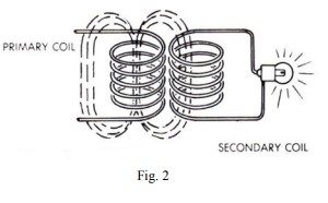
This is the principle of the ignition coil operation.
THE IGNITION SYSTEM
The ignition system consists of two separate circuits: The Primary Circuit and The Secondary Circuit.
The primary circuit consists of the battery, ignition switch, the primary winding of the coil, the points and condenser.
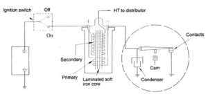
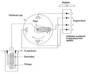
The Secondary circuit consists of the coil secondary winding, the high tension leads the distributor rotor and the spark plugs.
THE IGNITION COIL
The windings in the coil are not one above the other as illustrated in the figures above, but are one over the other. The secondary coil has about 20 000 turns of very fine wire (about the thickness of a human hair). Around the outside of this are about 250 turns if thicker wire to form the primary. Having the secondary inside the primary ensures all the secondary turns are cut by the magnetic field as it builds up.
There are also soft iron segments in the centre and around the windings which concentrated and strengthens the magnetic field.
IGNITION OPERATION
When the ignition switch and points are closed current flows from the battery through the ignition switch and the primary winding to the points. Then via earth back to the battery. Current flowing through the primary winding causes a magnetic field to build up; similar to that shown in Fig 2.
The speed of magnetic build up when the point are closed is too slow to induce a significant voltage into the secondary winding.
When the points open, however, the collapse of the magnetic field is assisted by the condenser and is fast enough to induce a voltage of up to 20 000 volts. More than enough, under normal running conditions, to jump the spark plug gap and ignite the fuel mixture in the cylinder.
CONDENSER OPERATION
As the distributor points open current continues to flow across the gap between the points for a short and until the gap is wide enough to stop the flow. This current slows down the collapse of the magnet field in the coil and reduces the strength of the secondary voltage. It also causes damaging arcing at the points. The condenser absorbs the current and so prevents arcing and allows a much more rapid collapse and high secondary output.
The condenser consists of two strips of metal foil separated from one another but will very low resistance between them. The resistance between the strips is less that the resistance across the opening points, therefore the electrons (current) flow into the condenser rather than jump the point gap.
POINT GAP
The point gap is critical in that it controls how long the points will be closed. Despite what we may think the effect of an electrical current is not instantaneous; it takes time for current to flow from one place to another and it takes time to establish an electro-magnet.
If the points are not closed for long enough (ie the gap is too wide) the magnetic field will not be able to reach full strength and the secondary voltage will be low.
If the points are closed for too long (ie gap is too small) the primary current will jump the gap and cause arcing.
You may have heard of the term “cam angle” or “cam dwell”. This refers to the number of degrees the distributor shaft turns while the points are closed. It is measured with a special meter while the engine is running.
FACTORS AFFECTING IGNITION PERFORMANCE
The actual voltage produced in the secondary winding depends on the resistance of the secondary circuit. Once the voltage is high enough to over-come the resistance a spark will jump the plug gap. The secondary circuit resistance depends on the type of high tension leads used, the gap between the end of the rotor and the distributor contacts, the type and condition of the plugs, the plug gap, the strength of the fuel mixture and the pressure in the cylinder.
The condition of the points, the point gap and the condition of the condenser will affect the amount of current flowing in the primary circuit and in turn the voltage output supplied to the spark plug.
The majority of vehicle break-downs are caused by the ignition system. Careful maintenance of the system will prevent most problems. I a problem does occur careful study of each component will tell you which part is not doing what it should.
Ray Mahony, Western Model A News, Aug/Sept 2015
Top of page
Simplified Model A Electrical Drawing
Notes:
- Positive ground (6 volts)
- Service bulletin is incorporated with ignition power coming from generator side of ammeter
- The points are grounded when the key is in the off position to prevent hot-wiring the points
- The horn circuit floats above ground; either side can be connected to power.
Note: Power to the brake light switch is routed through the light bail for no purpose. A suggested modification is to disconnect the power lead from the bail to the brake light switch at the switch and tape it back. Run a new wire from the protected side of the fuse to the brake light switch. In the event of a short circuit in the bail (which is a common electrical fault), the wire from the cutout to the bail can be disconnected and you can continue to drive during daylight hours and still have brake lights.

Tom Endy, July/Aug Ford Torque 2018
Top of page
Volt-Drop Testing
One of the difficulties with electrical systems is that you cannot see what is happening; you can only see the result. You can see the brightness of the light, you can see the spark produced in the ignition system, but just about everything else is left to the imagination. This makes it very difficult to identify what the cause of a problem is when things are not happening as they should. When mechanical components fail you can see, feel or hear the cause of the problem.
In many cases the cause of an electrical problem can be identified by a “VOLT DROP TEST”.
In one of my early articles you will recall that CURRENT is the movement of electrons (or electricity if you like) VOLTAGE is the pressure that pushes the electrons through the conductor (wire) and RESISTANCE acts against the voltage and will reduce the flow of current. It is the current that actual does the work, if you don’t get the required amount of current to the component it will not work. The major cause of this is either too much resistance or insufficient voltage.
If we take a simple circuit such as below we see that the voltage supplied (battery voltage –V1) is 12 volts. The voltage measured across the globe is also 12 volts (V2); this means all the voltage has been available to supply current to the globe.

If we add another resistor to the circuit (say another globe or dirty connection) voltage will be required to push current through that resistor as well as the first globe. Therefore there will be less voltage available to push the current through the first globe. With less current the light will be dull.
The VOLT DROP TEST is the method we use to find out where the resistance in a circuit is, and therefore identify why an electric circuit is not operating correctly.

This diagram shows the test sequence to diagnose starter problems. For the test you will need a voltmeter capable of reading less than 1 volt. (Any digital voltmeter can do this.)
The first thing is to establish that your battery is OK. With the voltmeter connected across the battery it should read 12 to 13 volts (V1). With the voltmeter still connected to the battery engage the starter and note the gauge reading (V2). The reading should be within ½ volt of V1. A small drop here is normal and indicates how much voltage is available to supply current to the starter motor. Now connect the voltmeter to the starter main terminal and the body (earth) of the starter. Engage the starter and note the gauge reading. A reading of more than ½ volt less that V2 indicates a problem: somewhere in the circuit there is unwanted resistance that is using voltage. Readings V4 and V5 combined will be the difference between V2 and V3 will start to identify where the problem is.

Connect the meter between the battery post and the starter terminal, (V4) a reading above ¼ volt indicated a problem. Check and clean all connections. If V4 is OK connect the meter between the body (earth) of the starter and the battery earth post. As with V4 if this reading (V5) is above ¼ volt disconnect and clean all terminals and cable connections.
Any electrical circuit can be tested in the same way. In a lighting circuit the voltage measured across the globe should be within ¼ volt of the battery voltage, if it’s not then check the voltage at any or all connections until you find a reading or reading that make up the difference. The problem is usually where the globe holder connects to the frame of body.
A voltmeter can be used to check the condition of your ignition points.
With the points closed and the ignition switched on, the voltage across the point should be no more than 0.2 volt.
A higher reading indicates the points need cleaning. A high reading here will mean high resistance in the points and result in poor ignition operation.
Ray Mahony, Western Model A News, Sept/Oct 2015
Top of page
Headlight Grounding
Good headlight illumination must have good grounding of the lamp sockets. This depends on making a ground to the chassis frame, by way of the reflectors, to the headlight housing, to the crossbar, to the mudguard braces and, finally, to the frame. Loose connections, rust, paint, etc result in a volt drop and inefficient lighting.
Here is a suggestion to easily cure this problem: Solder a wire to the primary lamp socket of each reflector and connect the lead directly to the frame. Use a dark coloured wire and conceal it by feeding it through the flexible conduits and carried between radiator and shell down to the front of the frame where it is bolted down at the splash pans. Connections must be made on bare metal.
Western Model A News, April 2016 (reprinted from a 1995 newsletter)
Top of page
Installing 6V LED Lights
Recently when I was having our 1931 Model A checked for Concessional License, it was suggested that I write an article for our Club about the LED lights that I reconfigured for a 6V operation. The circuit diagrams are available if anyone is interested and I am quite happy to help if anyone wants to go along the same track. The front indicator lights were bought from a Trailer Spares place. I decided that two each side would be more easily seen than one, and they weren’t expensive. It wasn’t hard to get the innards of one of these and rewire the four LEDs in pairs and each pair paralleled. The other three were also rewired. Each of these yellow LEDs has a Vmax of about 2.2Volts each, and consequently I would need a power supply that didn’t exceed about 4.4 volts. Altronics have a very suitable 1.5 Amp Voltage Regulator Kit for $13. With these, the SMDs need to be soldered by yourself. Not easy if you aren’t used to fitting these components. Jaycar sell an identical kit with the SMDs already soldered but at a much higher price. LEDs are sensitive to over voltage and I needed to get it right. These regulators have a very stable output.

The bracket was made of aluminium panel and bent as shown in the picture here.
One of the two 1/2” coach bolts that supports the headlamp bracket/rod was removed, placed in the lathe and bored for wiring. As these LED lights don’t have a high current consumption there was no need to make a large hole for the wiring.

The back of these indicator lamps needed to be tidied up a bit to cover the nuts and bolts holding each lamp to the alloy bracket. This was achieved by cutting down a plastic “Jiffy” box and securing it to the back with a few dabs of silicon. Easily removed if need be.

The rear lamps were a whole different story and much more complicated, because I was organising blinker, stop and tail into the one light.
These lamps originally could be operated from 12 or 24 volts and changeover was automatic when they were connected, as all the electronics needed to do this was built in. I needed to remove the innards from the lens part and black backing plate, salvage the LEDs, discard the old circuit board what was left of it then make up a new circuit with veroboard.
The yellow indicator LEDs weren’t much of a problem. These were configured as seven pairs all paralleled and running from 4.4volt regulators.

The red LEDs were also configured in pairs that were paralleled (these operate on a lower voltage Vmax of about 1.9 volts each) and I wanted the stop lamps to be a little brighter than the Park Lamp section so two more Voltage regulators were used and three diodes also used in the circuit. The reason for this is more easily understood from the circuit diagram that I have if anyone is interested.
After the circuit board was installed and tested I sealed the circuit with Araldite.
For indicators at the beginning, I had made up an electronic timer on a little circuit board using about 1/2 dozen components and a 555 timer. This didn’t have enough grunt to drive the LEDs so I made up a “solid state relay” if you could call it that, using a Darlington pair of transistors capable of about 1 amp output. This worked fine until I started the engine. Electrical interference made it go haywire and I never found a way to fix it. It was back to the good old indicator “can” to control the timing but that had its problems too. The LEDs never had enough amperage requirement to make the indicator “can “ work. But I got around that as well. The electrical components of the indicator stalk on the steering column was also modified.
All in all quite a good outcome and learning experience but I never expected it to take so long. I am not an electronic expert by any means and quite happy to listen to someone else.
John Scobie, Western Model A News, Jan/Feb 2015
Top of page
Dashboard Lamp
I have always found the instrument panel light on my Model A to be too bright (and too hot! Ouch!). I would turn mine on for a few seconds, and then turn it right back off.
Here is a simple fix: put a 12-volt, 3 candle-power tail-light bulb in your 6-volt Model A instrument panel. That would be a #67 bulb, available at any auto parts store. Instead of being so bright, it will glow a nice, soft orange colour because it’s operating at half of the voltage it was designed for. Once your eyes get used to the dark, it gives all the light you need to see the instruments. You will gladly leave it on for the entire night drive.
P.S. The bulb number to do this on a car that has been converted to 12 volts is a #623 bulb. Harder to find, usually special order.
Jim Cannon, 2017 MAFCA Technical Director
Top of page
Isolating an Electrical Fault
Most Model A owners have installed a fuse mod on the top of their starter. This is certainly a prudent thing to do: a blown fuse is much better than having a fire in the car.
Once a blown fuse has occurred, the next step is to determine where the short circuit exists that caused it to blow. This can be accomplished rather quickly by a method of isolation. There are three areas on the car where a short circuit is most likely to occur.
- In the light bail located at the bottom of the steering column, which consists of all the switching circuitry for the car’s lights. This is the most common fault area.
- Inside the terminal box located on the firewall where a number of connections come together and can easily short-out against the armoured ignition cable.
- Behind the dash panel where connections to the ammeter and dash light are located that can easily short-out against the dash.
The first effort to isolate the fault is to unhook the 3 wires attached to the terminal post on the cutout switch, which sits on top of the generator. If you have an alternator, the 3 wires are attached to the output terminal post of the alternator. Disconnect the 3 wires and spread them out so they don’t touch anything.
One of the three wires comes from the terminal box on the firewall and provides battery power. A second wire runs down to the light bail, and the third wire goes off to the ahoogah horn.
Install a new fuse. If it does not blow, you have eliminated the terminal block on the firewall and the dash panel as the culprit. If there was a short in either of these two places, it would have blown the new fuse. Next, connect the wire from the terminal block to the wire that runs to the ahoogah horn. If the fuse does not blow, you have eliminated the ahoogah horn. Next, hook these two wires back onto the terminal post of either the cutout or the alternator. If the fuse does not blow, you have eliminated the cutout, generator or alternator. This leaves only the light bail as the likely culprit.
Inside the light bail is a rat’s nest of wires and switch contacts that could be oil soaked from a leaky steering box. If the light bail assembly is a poor quality repro, chances are there are wire whiskers and poor connections involved. If you are out on the road, it is best to fool with further trouble shooting of the light bail at home. You can drive the car with the light wire bail disconnected. Just keep in mind you won’t have any lights, including brake lights.
If a new fuse blew after you installed it after disconnecting the three wires from the cutout, the fault is likely in the terminal block on the firewall or behind the dash panel, and not in the light bail, ahoogah horn, cutout, generator or alternator.
Start with the terminal box. Remove the cover and inspect for loose or shorting wires. A poor quality repro terminal box can also have one of the terminal threaded shafts shorted out behind the box. It is possible for the threaded shaft to back-off and touch the firewall.
If the terminal box appears OK, remove the dash panel and inspect for loose and shirted wires on the back of the ammeter.
If you follow this procedure, you will quickly locate the fault 95% of the time. However, a subtle electrical fault could possibly be lurking somewhere else that may not be as obvious.

This particular Model A has a second fuse circuit to accommodate a Borg Warner overdrive. The tie wraps are to provide a means to easily remove fuses when the car is not in use.
Tom Endy, Ford Torque July/Aug 2018
Reading the Ammeter
The ammeter is a very useful instrument that tells us much about the electrical system in our Model A Ford. This is especially true when we understand how current flows in the vehicle’s circuits.
If no reading is seen on the ammeter scale while the engine is being cranked, then the ignition current is not flowing because the low voltage circuit is open. A switch that is not turned on is the same as an open circuit. The ignition breaker points inside the distributor may not be closing to complete the circuit, or the ignition switch or its cable may be defective. A broken pig-tail wire inside the distributor is another possible cause of an open circuit.

A long bolt with stop nuts and a jumper wire to the distributor terminals of the ignition coil will bypass a defective ignition switch or cable in an emergency.

Another emergency jumper for the ignition uses the end of an old cable and jumper wire with an alligator clip.
When you finish driving, stop the engine and take a final look at the ammeter before leaving the driver’s seat. If any switch is not turned off, a discharge reading is seen on the ammeter. Check the ignition switch. If the breaker points are closed, with the switch turned on, current flows steadily into the ignition coil, rather than pulses of current that are normal when the engine is running. After some time, the steady flow of current will overheat or burn out the ignition coil, and overheat the breaker points.
The ammeter warns you of a problem before it becomes serious.
If the ammeter registers a heavy discharge current when the engine is stopped, the likely cause is that the generator cutout contacts have stuck closed. Disconnect the the wire from the battery terminal of the cutout to stop the flow of current into the generator. (Sometimes a sharp rap with a wrench will dislodge the stuck contacts.) Current from the battery can burn out the generator! If the vehicle is to be driven before the cutout can be repaired or replaced, ground the generator output terminal (the opposite cutout terminal) to prevent the generator from destroying itself when the engine is running. With a defective cutout, the generator output may reach 18 amps, and the excess is dissipated as heat.

A jumper wire connected across the terminal wing nuts can test for loose connections or bypass a defective ammeter.
Anytime the generator is not connected to the battery circuit, the output terminal must be grounded to protect the generator if you are not sure as to the cause of the trouble. A good battery will run the vehicle all day without charging current from the generator.
If cutout contacts fail to close when they should (when the engine is running and generator “charging”), the charge is seen on the ammeter. A jumper wire can be clipped across the cutout terminals to enable the generator to charge the battery. When the generator is not running, remove the jumper wire as it the same as stuck cutout contacts.
A broken wire or connection inside the generator, worn brushes that fail to seat to the commutator bars of the armature, or open field coil windings will result in a no charge reading on the ammeter.

This simple home-made test light can be used to test voltage or to time the ignition breaker points.
If no discharge reading is found on the ammeter when a switch is turned on, an open circuit is indicated. If a lighting circuit(such as parking lights) is turned on and no discharge is seen, an open circuit exists. This may be due to burned-out bulbs, as they create an open circuit. If no lights burn, but the horn will operate, or the engine runs, the fault may be in the wiring harness, the light switch, or all of the bulbs are burned-out. This can happen if any of the battery cable ends are loose. Loose connections at the battery posts, at the starter switch terminal, or the ground strap to the chassis allow the generator voltage to increase to a very high level, and the bulbs are burned-out when the light circuits are turned on with the engine running.
Paul Moller, The Restorer, as reprinted in Western Model A News, Jan 2016
Top of page
Points
The specification for the distributor contact points is for an opening of between 0.018 and 0.022 inch. A gradual decline in engine performance can be caused by the points closing so that the gap is below the minimum specified. This in affect means that the timing is retarded. The fibre rubbing surface of the points may wear rapidly when new points are installed and also if a lubricant is not used on the distributor cam lobes. Cam lubricant is available for this purpose or a small amount of vaseline may be used.
To check and adjust the points opening a set of feeler gauges is used. As an alternative to feeler gauges check the thickness of cards etc in your wallet as these can range from 0.010 to 0.030 inch. Select one around 0.020 inch and use this card to check the points if your feeler gauges are not available.
John Moorehead, MARC WA Newsletter Feb 2012
A standard paper clip has a diameter of .036. Thus, if someday you find yourself without a .035 gauge with which to check the Model A spark gap, just use an ordinary paper clip.
Ray Mahony, Western Model A News, June 2013
Top of page
Rotor Spark Gaps
To ensure efficient and smooth operation of the ignition system, three gap settings need to be checked. Whilst the contact breaker points and spark plug gaps are normally checked, the third gap i.e. rotor gap is often overlooked.
This gap is measured between the tip of the rotor blade terminal and each of the four prongs inside the distributor body. For optimum ignition performance it is recommended that this gap be between 0.025 inch (0.63 mm) and 0.030 inch (0.76 mm). Before making any adjustments, check that the distributor shaft is not loose in the distributor bushes causing lateral movement of the shaft and hence inconsistent readings. The rotor should also be firm on the distributor cam.
After checking and if adjustment is necessary, start at the prong with the widest gap. Carefully bend the rotor blade to position in the centre and set the gap accordingly. The remaining prongs can then be filed with a fine points file to achieve the correct clearance gap.
John Moorehead, Western Model A News, Jan 2013
Top of page
Spark Advance
Are you getting all the spark advance you are supposed to ?
The next time you are poking around under the hood, check your spark advance at the distributor. With the spark lever fully up, make sure that the arm sticking out of the distributor (the breaker plate arm) is fully touching the side of the opening in the distributor body closest the the exhaust manifold. Then, with the engine not running, pull the spark lever all the way down and confirm that the breaker plate arm is now fully touching the other side of the opening in the distributor body.
If its not, you’re not getting all the spark advance you should be getting.
You may need to rotate your steering column (cars with 2-tooth sector steering box), or bend the little spark lever on the column to get the breaker plate to move the full range.
Jim Cannon, MAFCA Technical Director, Script A News July 2018
Top of page
Modern Condensers
Hi members in the West, upon reading your newsletter and Glad’s ailments, I would like to share some problems recently with capacitor aka condenser supplied from USA breaking down and very little spark. We are now using Bosch—GF79—F005X04536-4BH made in Japan (not Turkey or Asia) available from Bursten, Repco etc. It fits straight in, I know of four As using Bosch with good results. It may not be Glad’s ailments, but I hope she gets better soon. Looking forward to next newsletter.
PS: this is for 12 volt, modern points
Nev Pearce (MAFC Qld), Western Model A News, July 2018
Top of page
Handy Bypass Wire
This is a simple device that will help you diagnose trouble in your electrical system and. in some cases, offer a temporary solution to get you home.
It is simply a length of wire, about 500mm long with alligator clips attached to each end.
- Connected across the terminals of the junction box can bypass a faulty ammeter
- Use a longer bolt in the distributor terminal of the condenser. Connect this to the red coil wire using bypass wire and you can illuminate a defective ignition switch or faulty armoured cable.
- If the cutout contacts fail to close, you can bypass the cutout to charge the battery.
- It can be used to ground the generator output terminal if the cutout terminal is stuck closed.
- Plus it can be used to test resistance (or voltage loss) in the horn and lighting circuits b by-passing switches and connectors.
- For that matter, it could be used to test contacts and wires hidden in bodywork or conduits
Five minutes to make – could save you hours!
Andrew Millar, originally published in South Australia’s Model A Torque,
reprinted in Western Model A News, March 2016
Top of page
Terminal Box
Over time I have had the terminals come loose in a terminal box. I suggest the next time you have it removed or fit a new one it is a good idea to Araldite (or similar) the two screw heads into the plastic base. Make sure they are tight first. The two green spots on my photo show the two screw heads to glue.
Remember, only fill the hole until it is level otherwise they will prevent the box mounting flush with the firewall.

Alan Jeffree, Western Model A News, Nov 2015
Top of page
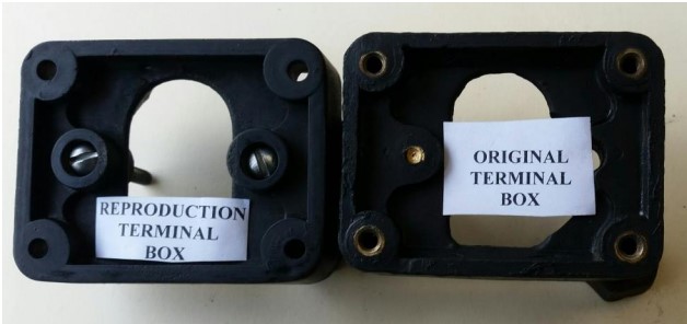
Terminal Box Overheating
The original terminal box in the Model A had the terminal screws moulded within the plastic (Bakelite type material) box and could not move to come in contact the metal body. (Refer attached photograph) Also for securing the box to the body, brass inserts with internal threads were incorporated in the plastic box. The replacement terminal box from suppliers has the terminal screws held in place with captive nut within the box moulding. If these nuts are not positioned correctly at the time of installation or become loose, the head of the screw may move to contact the metal body causing arcing and overheating. The amount of movement is as little as 0.030 inch (0.75mm).
To ensure that no electrical contact between the head of the screws and the metal body, rubber plugs or similar can be cut and fitted in the recess over the head of the screws. These insulating barriers can be held in place using an adhesive.
Another point to watch is the firmness of the four screws holding the terminal box to the body. As the screws tighten onto the plastic and not brass inserts as in the original box, they can become loose.
An additional precaution is to install an in-line fuse to protect the electrical system. Originally the Model A electrical wiring did not have any short circuit protection. The fuse mount is available from parts suppliers.
John Moorehead, Western Model A News, Sept 2017
Top of page
Fuse Installation
Many of us like to install a fuse on our Model A to prevent a small electrical problem from becoming an even bigger one. You’ve all seen them, the little fuse holder that mounts to the side of the starter switch, holds a little glass fuse, and connects to the solid yellow wire. A great idea, but it has a few weaknesses. First, an open fuse holder like this will eventually corrode as it is exposed to the elements. Oil mist and road grime will collect in it and give you a bad connection. Vibration from the engine will loosen up the little metal clips that the fuse snaps down into. With time, this little fuse holder becomes a trouble spot in your electrical system. I’ve seen it several times on tours.
It is possible to purchase a moulded fuse holder with a waterproof cover that snaps securely over the fuse (see photo). It uses a blade-type fuse that can be obtained in any amp rating you need. They work on 6 volt or 12 volt cars. You splice it in to the wiring harness and solder the connections (not just crimp them on). Cover with woven loom to hide everything except the fuse itself and it disappears (mostly).

Much better.
I’m often asked where to put the fuse. If you only put it on the solid yellow wire at the starter switch, if it ever blows while driving, your engine will die right there. This might be at a very bad time to have no power, when you really need your engine running. It could be dangerous. Most shorts that would cause a fuse to blow are in the lights or the horn. I recommend putting fuses in the two solid yellow wires coming off the generator (alternator) that go to the headlight switch and the horn. If one of these fuses blows, you won’t have lights or a horn, but your engine will still run. Figure out how much current your lights draw and put a fuse about 25% bigger than that on that wire. The same with the horn wire. If you accidentally use too small a fuse, it will blow and you replace it with one of a slightly higher amp rating.
Once you have installed these two fuses, then you add a third fuse to the yellow wire coming off the starter switch. Use a fuse amperage here that is a bit bigger than the ones you used for the lights and horn. This becomes your protection against a really big problem in all of the wires besides lights and horn (like ammeter and associated wires). This fuse should not blow if you have a short in the lights or horn, so the engine will keep running and you can limp home (without horn or stoplights – be careful). But if you have a major short, one capable of starting a fire, the 3rd fuse will blow and save your car. This is one of my more complicated Tech Tips. I hope it helps your car stay safe and reliable. I’m always open to feedback.
Have a Model A Day!
Jim
Jim Cannon, MAFCA, Western Model A News, Aug 2020
Top of page
Ignition Switch Lubrication
Original pop-out switches grow sticky with age due to gum and electrolysis. Before junking the switch or waiting for the key to break-off, try this solution: Turn the key until the switch pops-out. Under the first “F” in the word “Off”, drill a 1/16” hole carefully through the brass shell. Now the cylinder can be loosened with WD-40 using the plastic tube.
Western Model A News, September 1993
Top of page
Horn Rod Clip Tool
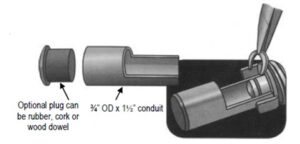
An easy to make tool to seat a horn rod clip
This tool will help to seat the clip on the end of the horn rod, which can be frustrating and sometimes painful.
The tool is a short piece of 3/4” OD conduit about 1½” long. Cut with a hacksaw half way through the conduit vertically and horizontally, taking ¼ of the piece of conduit out. An optional plug can be inserted in the end of the tube to catch the clip if it falls. Note: You may need to squeeze the half round portion a little to fit the spider.
To use:
1. Move the light switch 90 degrees, so that the forks of the spider are horizontal.
2. Hold the horn rod down using a ruler or similar item.
3. Set the spring and the spider on the horn rod end and press the tube to expose the notch that the clip goes into.
4. Seat the clip using needle nose pliers or forceps.
Dick Przywitowski (taken from The AaaaOOOgah! LaFayette, Colorado ), as appeared in Western Model A News, March 2021
Top of page
Ignition Cam Screw
I have helped a few Model A owners with an unusual problem: For no reason at all, their distributor goes “out of time”. They lose power and have to limp home. They reset the timing and the car runs great again, but after a while the same thing happens and they limp home. Gremlins? No.
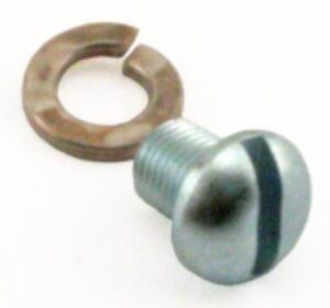
The problem is that the ignition cam screw may not hold the cam down tightly to the distributor shaft. After a bit of driving, the cam rotates into a more and more “retarded” position and the engine loses power. In spite of getting out a big screw driver and tightening the screw as much as possible, the cam still moves on them. Why is this? The SCREW that they are using is too long for the hole that is drilled and tapped in the top of the distributor shaft.
Some reproduction screws are just too long. Or the hole in the reproduction distributor shaft is too shallow. Or both! Whatever the case, the screw bottoms out in the hole and jams up tight before the cam is properly locked down on the shaft. So the cam moves.
The simple fix is to add a washer under the head of the cam screw. Now the cam will get locked down well before the screw bottoms out in the hole. You also want to inspect the underside of the cam; it should have ridges that help lock it down on the shaft. Once the screw is tight, put the rotor on the cam and gently try to turn it on the distributor shaft. It should not move.
If you or a friend encounters this problem with the engine going out of time, I hope my little Tip does the trick for you.
Have a Model A Day
Jim Cannon, MAFCA, as appeared in Western Model A News, May 2022
Top of page
LED Headlight Flickering
Those Flickering LED Headlights!
Even though LED headlights have revolutionized night-time driving for Model A owners with significantly improved headlight brightness, these LEDs will sometimes flicker, especially when the engine is idling. Fortunately, it’s pretty easy to eliminate the flickering by trying several simple fixes.
First, running an extra ground wire from the headlight socket inside the headlight bucket to a good ground on the engine or car frame can only help. For aesthetic reasons, try to run the ground wire inside the flexible metal conduit between the headlight and radiator shell. Also, be sure to solder the ground wire to the headlight socket assembly inside the headlight bucket. Don’t rely solely on a mechanical connection; rust and paint often interfere with electrical ground connections through bolts and the headlight bar after 90+ years.
Next, examine the two electrical solder contacts on the bottom of the LED: Are they gouged? If so, remelt the solder contacts with a solder gun until they are smooth and rounded. (A soldering iron will work; it will just take longer to get a satisfactory result.) This will often eliminate flickering, as the solder contacts are soft and easily deformed by repeated installation of the LED into the headlight socket.
If neither of the first two solutions eliminates the flickering, check for tightness of fit of the LED in the headlight socket. Many reproduction headlight sockets are made of thinner metal than the originals and LEDs are often a loose fit in these sockets and can wiggle around. Vibration from an idling engine can cause flickering for this reason.
I recently located a set of original headlight sockets and was surprised at how much heavier these are than the reproduction sockets I installed over 30 years ago.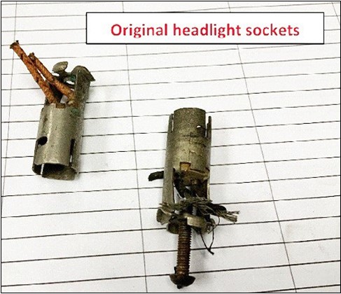
After splicing in new wires, insulating the connections with heat shrink tubing, and installing these in the headlight buckets on my roadster, the flickering problem was eliminated. LED headlights are a snug fit in original sockets !
There are, however, a couple of things to be aware of: First, unsoldering the original wiring directly from the spring-loaded contact pins in the original sockets can disrupt the alignment of the pins, possibly causing a short to the body of the socket. If at all possible, splice new wiring in to the original socket wires using a soldered connection, insulated with heat-shrink tubing. This will preserve the contact pin alignment. Second, do not over-tighten the focus screw at the back of the socket assembly when mounting the socket assembly in the headlight bucket; screwing it in too far will cause it to short the wiring connections to ground. With focused beam LED headlights, this screw no longer affects the headlight beam focus anyway; its only purpose is to hold the headlight socket assembly to the headlight bucket.
So, if your new LED headlights are flickering, find and install a set of original headlight bulb sockets – you’ll be glad you did!
Jim Conaway, Script A News Aug 2023, as appeared in Western Model A News, Feb 2024
Top of page
Ignition Misfires
We’ve all experienced it. When the engine is cold and first started up, the engine is running rough and you can tell not all 4 cylinders are firing. It usually clears up in under a minute. But later, when the engine is warm, you should not feel a miss when climbing a hill or accelerating into traffic. If the power is just not there, like you know it should be, where to look? It could be a carburettor problem, but don’t overlook fouled spark plugs and problems in the distributor.
Check the point gap in the distributor. The cam follower wears as you drive and the point gap closes down, giving a weak spark. So check it and increase the gap back to 0.020” if needed. While you are there, look for burned points and clean them up or replace them; you might have a bad or weak condenser.
Look at the rotor. Make sure the black flat spring is touching the underside of the cap, and is not burned up. Wipe off any oil film on the rotor.
Look at the underside of the distributor cap. Inspect the graphite button on the underside. I have seen caps with the entire button broken off and missing.
Look at the inside of the distributor body (the black plastic piece). Look for an oil and dirt film on the inside. Wipe it out with a clean cloth. Look for “carbon tracks” on the inside of the cap, where the spark is jumping down to ground on the metal housing (see photo). Replace if needed.
![]()
Jim Canon, MAFCA, as appeared in Western Model A News, April 2024
Top of page
Fuse Block Terminal Shorts
We started to solve a problem based on the wiring for the horn and found it was something else unrelated. Such fun. What we experienced may help others to avoid a similar problem.
The horn on my 1931 Four Door sounds anaemic. Perhaps seriously so. Not being afraid to blunder on where I know little, I removed it to do the usual things to smarten up the sound. Before I removed it, I took out the fuse. Yes, The fuse. There is only one. I cleaned up the horn, bench tested it and put it back on the car. All good. I put the fuse back in the block making the system live. Enter flash of blue and yellow and a sound much like Zot! My fuse blew. Did it again with the same result. I began to be gun shy about further attempts. My rapid conclusion: the horn was killing my fuse. The question was how.
I called my son Geoff as he is far more knowledgeable about things electrical. We followed the Les Andrews blue manual trouble shooting chart to no avail. We disconnected the horn and, eventually the wire below the generator to isolate the problem. No joy. At this point we were lost. Geoff was playing with the fuse block and found the rear mount for the fuse was loose. Geoff suggested that the problem was in the fuse block. I knew how to address this one. Money solves many things. A phone call and the part was on its way.
On a warm November day, Geoff installed the new fuse block. No blue and yellow flash. No Zot. And the car resumed doing all the things it was supposed to do. Success. The new fuse block is a better design so the problem we experienced will not happen.
Now to the reason for this epistle. Below is a picture of the unhappy fuse block. When we removed it, the nut in the middle was loose showing about 1/8’ of thread below it. We found that if we tried to install a fuse, the bolt assembly was pushed down shorting on the starter. If the nut is tight, no problem. The Message:
Look at the fuse block on your car. If it is the one in the image, make sure the lower nut is tight or your future includes blue/yellow spark and Zot!

Ted Lobley, Stampede City A’s (Script A News, Aug 2023, as appeared in Western Model A News, Dec 2024
Top of page
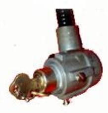
Horn Maintenance
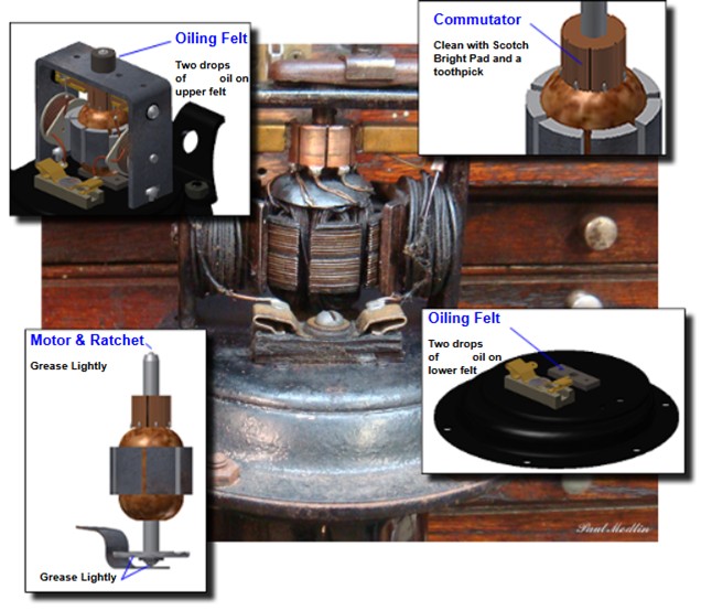
Oiling
Tools and Supplies:
– Flat blade screw driver
– Scotch Bright pad (or similar)
– Sewing machine oil
– Kerosene
– Toothpicks
Procedure:
1. Remove the dirt build up from the upper and lower oiling felts. Clean with kerosene and pad dry.
2. Polish the commutator with a Scotch Bright pad. Clean between the gaps with a toothpick.
3. Apply two drops of sewing machine oil to both the upper and lower oiling felts.
4. Lightly grease the upper and lower tips of the motor shaft, as well as the bottom of the ratchet
Paul R.Modlin, modelabasics.com, as appeared in Western Model A News, Nov 2025
Top of page
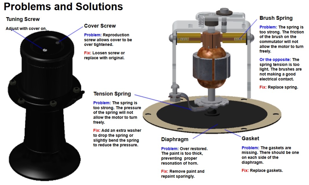
Horn Problems and Remedies
unknown source, as appeared in Western Model A News, Feb 2026
Top of page
Distributor Shaft Lubrication
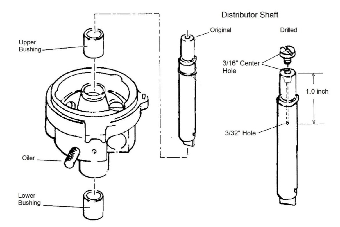
Ford recommends lubricating the distributor shaft every 500 miles by adding a few drops of oil at the spring-loaded oiler on the side of the distributor. This effectively oils the lower bushing only. Proper lubrication of the upper bushing is a problem however. The distributor shaft and cam screw should be drilled to allow oil to the upper bushing. You may order already drilled shafts from the parts suppliers or do it yourself.
Drill a 3/16” hole down the centre of the shaft 1” deep, and a 3/32” hole through the side. Drill a 3/16” hole through the centre of the cam screw. Drilling the shaft is not difficult as the drill centres itself for the 3/16” hole.
If it squeaks it’s just asking for attention !
Willie Priaulx, Central Iowa A’s, Script A News Feb 2026, as appeared in Western Model A News, April 2026
Top of page