
Carby & Fuel
Simplified Zenith Carburettor
Idle Problems with the Zenith Carburettor
Setting the Air Idle Screw
Choke Rod (Mixture Screw)
Jets
Carburettors – all you need to know
Carburettor Float Level Setting
Fuel Blockages
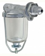
Fuel Bowl Filters
Fuel Gauge Restoration
Fuel Line Fittings
Petrol Tank Rust
Leaking Fuel Fittings
Petrol Cap Air Breathing
Petrol Tank Long Term Storage
Petrol Tank Cleaning
Shut-Off Valve
Stopping at Idle / Throttle Plates
Idle Problems with Zenith Carburettor
Members have expressed concerns regarding uneven idle or stopping with the Zenith carburettor in their Model A. The most common cause is foreign matter in the idle jet. The opening in this jet is only 0.021 inch in diameter and hence it can become partially blocked even with a filter in the fuel line.
Another cause is an incorrect fuel level in the carburettor bowl. When braking hard when the fuel level is below the specified position the fuel will move resulting in insufficient feed to the idle jet. The setting for the float to control the fuel level can be set at nominally 0.625 inch above the machine surface of the inverted upper body (refer to Model A manuals). A more accurate method is to remove the drain plug and position a clear plastic tube with fitting to the outlet and raise the tube above the upper body. With the fuel on the petrol in the tube should be approximately 0 .625 inch below the gasket joining the two parts of the body.
Another, not so obvious, problem is the under cut section in the secondary well in the lower body of the carburettor, (P/No/ A-9545). In early production the secondary well had the undercut section positioned below the hole to the compensating jet thus affecting fuel supply. To check your carburettor it is only necessary to remove the compensating jet and with a soft pencil mark the well via the jet hole and then remove the well to check. The design of the secondary well was changed in 1930 providing a new location for the undercut section.
John Moorehead, Western Model A News March 2017
Top of page
Setting the Air Idle Screw
(Knurled screw with short spring situated on the top section of the carburettor)
- Start your Model A and warm it up to operating temperature.
- Push the advance lever (left hand lever) all the way up.
- With the vehicle idling adjust the Air Idle screw as follows. Turn it in (CW, which is richer) until the engine starts to run poorly. Note the position from the slot.
- Now adjust it CCW (leaner) until the engine starts to run smoothly. Continue turning it CCW until the engine starts to run poorly. Note the position (how many turns).
- Turn the idle screw back (CW) to half way back between the positions found in step 4.
Somewhere a little back and /or forward you will find where your engine runs smoothest.
This adjustment may not have a great effect on some Model A carburettors. This usually means there is an air leak into your carburettor. Often this is wear in the throttle shaft or a gasket is damaged.
If you ever need to remove the Air adjusting jet, turn it in all the way in and turn it out one, to one and a half turns for a trial start then adjust as described above.
Alan Jeffree, Western Model A News May 2012
Top of page
Choke rod (Mixture Screw)
We all know about the choke rod, but this is also the mixture screw which controls how much petrol goes into the engine.
With the engine stopped, turn the choke rod clockwise until it stops. You will notice where the little raised marker is pointing. Then turn it anti-clockwise about one turn if the engine is cold, for start up. Only half a turn if the engine is warm. After a few minutes running, try turning it clockwise, then anti-clockwise, until the engine runs smoothly and the engine revs without faltering.
Each carby has different amounts of wear, so experiment a little at a time so that your Model A runs and performs at its best. Some will run closed when hot! You should have it somewhere between closed (clockwise) and one turn open.
Alan Jeffree, Western Model A News Nov 2011
Top of page
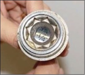
Jets
The jets used in the Zenith carburettors have been reproduced as replacement parts in many forms. The jets must be designed to eject a fuel spray and not a stream of fuel.
The size of each jet orifice should be checked using number drills or similar to ensure the correct hole diameter. Whilst over the years there were some minor variations the following sizes are generally accepted as satisfactory:
| Jet | Inch | mm | Drill |
|---|---|---|---|
| Compensator | 0.037" | 0.94 | 63 |
| Main | 0.035" | 0.89 | 65 |
| Cap | 0.036" | 0.91 | 64 |
| Idling | 0.021" | 0.53 | 75 |
Another very important point is the design of the jet tip. Some jet tips are raised and rounded or pointed. These designs produce a poor quality air/fuel mixture. The correct tip for the Main and Cap jets is concave with the orifice at the bottom of the concave tip.
John Moorehead, Western Model A News May 2014
mm drill sizes and drill numbers added by Ian Steer, Oct 2018
Top of page
Fuel Blockages
If your Model A staggers to the side of the road, starved of fuel, there are a few obvious points to check:
- Dirt or water in the carburettor
- Clogged vent in fuel cap (or wrong cap from radiator)
- Clogged fuel filter
- Clogged fuel line
- Kinked fuel line
- Loose fuel line fittings
- Vapour lock
- Main jet dirty
- Is the tap fully on?
- Is the outlet hole in the fuel tank clear?
- Has the choke arm nut come adrift allowing the choke flap to close – causing flooding?
- Is the carburettor float set correctly?
If you disconnect the fuel line from the carburettor and fuel does not run out, you have immediately isolated one problem. Try blowing back down the fuel line to clear the blockage. If fuel does start to run through, you may have cleared the system for a while, but probably have rust in the tank.
One way to clean out the tank is:
- Disconnect battery
- Remove floor boards
- Drain fuel tank
- Remove shut-off valve
- Fill tank with water, then let it drain out where the shut-off valve was.
- Repeat as many times as it takes to thoroughly clean out the tank.
If you are worried about a few drops of water, leave the car in the sun for a while before re-assembling the fuel lines and refilling the tank.
Western Model A News April 2016 (reprinted from a Western Model A News 1995 Newsletter)
Top of page
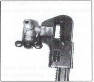
Fuel Line Fittings
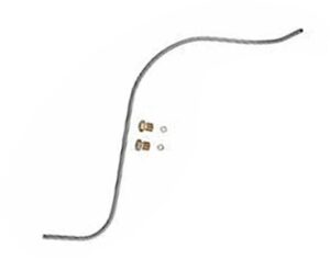
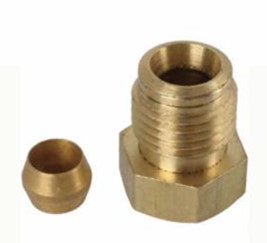
When installing a new fuel line between the sediment bowl and the carburetor, you want to get the little brass ferrule locked down on the tubing about 1/8″ from the end of the tubing. It is difficult to see where the ferrule is located on the tubing though, when the end is inside the carburetor or the sediment bowl. Here’s my little trick to getting it where you want it.
On the bench, before installing anything on the car, slip the tube nut and ferrule on the end of the fuel line like it will be installed on the car. See the photo. Place the ferrule on the tubing with 1/8″ of tubing showing on the end. Gently press the nut up against the ferrule and mark that location with a little piece of masking tape.
Now when you install the tubing on the carburetor or sediment bowl, you hold the tubing in so that the tape is right at the edge of the nut while you tighten the nut. When the ferrule gets clamped down on the tubing, it will be in the right spot. You can take it apart to check.
I apply a few drops of oil to the threads of the nut and to the ferrule when tightening it all up for the first time, to help everything turn smoothly as it’s being clamped in place. Teflon tape should not be needed on these tube nuts and ferrules; they are designed to seal with just the nut being tightened. It does not hurt to put a thin film on non-hardening sealant on the ferrule, though, before installing, for extra protection against weeping fuel.
Western Model A News October 2020 (Jim Cannon, MAFCA)
Top of page
Petrol Tank Rust
If you have a Model A which keeps having dirt in the carby problems, the following suggestions came from long time club member, Steve Read. I have used it with great success. Rust in your tank is usually the problem and if the vehicle is complete it is a huge task to take out your tank to work on it!! Rust is metal which has disintegrated, but it is still steel which is attracted to a magnet.
Find a strong magnet which will fit into your tank through the filler. I broke a magnet from a scrapped microwave until I had a piece fairly large, I then fitted a thin wire cage around it with a loop on top. The loop is to position the magnet into the tank close to, but not too close to the internal outlet. Use a torch to check where the internal outlet is and avoid damaging the filter which is attached to the shut off valve (part number A9193-T) The loop does two things it allows you to position it and retrieve it if necessary. The magnet needs to sit on the bottom of the tank where the rust accumulates. Your magnet traps the rust particles instead of them going into the fuel outlet inside your tank. The second part to this concept, is to position a small magnet inside the carby bowl close to the screw-in compensator jet. It needs to be small so it doesn’t interfere with the float. You can only do this if you have an original cast steel carburettor as it will move around in an aluminium bowl and could block the jet.
To break the microwave magnet I placed it in a strong cloth and hit it with a hammer. The magnet is very brittle and pieces will fly, which is why I wrapped it to protect eyes etc. From the breaking, you get small pieces suitable for the carby.
When cleaning out the carby at any stage, take out the carby magnet and give it a blow with compressed air to remove the particles of rust which may have accumulated on it. I have never removed the tank one.
You can buy all sizes of magnet so this would be a safer approach!
One person I passed this tip on to suggested that a strong magnet on the underside of the tank may do the same job!
Alan Jeffree, Western Model A News Oct 2013
Top of page
Leaking Fuel Fittings
A little problem I have experienced over the years, and not only with the Model A, is that little fuel leak or weep from a pipe union or drain plug.
To solve the problem simply remove the offending part, clean thoroughly and paint with fingernail polish. Allow the polish to dry thoroughly before letting the petrol to contact.
Once dry, the petrol will not dissolve the polish.
Ray Mahony, Western Model A News Feb 2013
Top of page
Petrol Cap Air Breathing
If your Model A stops due to lack of fuel, the first check should be for a vacuum lock in the fuel tank. As the Model A fuel system relies on gravity feed, it is essential that atmospheric pressure is maintained in the space between the fuel and the inside of the tank. The fuel cap vent holes must be clean and free to allow the tank to breathe. The fuel cap and radiator cap are similar but they are different in structure in that the fuel cap is vented.
This problem is very real and I know of three cases including our first run in our Model A. After coming to a halt after driving for some time I received assistance from fellow Club members. When the fuel cap was removed to check the fuel level I heard the rush of air into the tank as the atmospheric pressure was restored. The cap was left loose for the remainder of the run until the vent holes could be cleaned.
John Moorehead, Western Model A News March 2013
Top of page
Petrol Tank Long Term Storage
Taken from the Model A Ford Bulletins – If you are going to store your Model A
for some months it is a good idea to store it with a full or completely empty tank. If
your tank is partially full; in the case of a cold day turning warm or more humid ,
the cold petrol in the tank will cause condensation to form on the inside of the tank
resulting in rust on the exposed surfaces.
Located by Alan Jeffree, Western Model A News July 2013
Top of page
Petrol Tank Cleaning
I have found on just about every restoration under-taken, there is corrosion inside the A Model fuel tank. Here is my method of cleaning one out.
The tank must be out of the vehicle. First all fixtures to the tank must be removed. Next you have to seal all openings by using something substantial. I use plastic lids off ice cream containers and cut a piece the size of the fuel gauge opening which you hold in place by using the screw-in ring of the old gauge. You may need several thicknesses to fill the depth. Use an old fuel cap to seal the top. Block off the fuel outlet with an old tap or similar.
The procedure – hire or borrow a small cement mixer (electric is quieter). Temporarily set the tank on the mouth of the mixer, some soft packing here is good. Manufacture 4×1/4 “ holding bolts to attach the tank firmly to the rim of the mixer. 1928 and 29 tanks need 2 long and two shorter with spacers. 1930/31 tanks need 4 long bolts. The bolts must have a very tight 180 degrees bend on one end which I put on the bench grinder to give a sharp edge. Without going into too much detail here, manufacture a secure hold for the tank to the rim of your mixer with padding to protect it. Next pour 8 to 10 kg of 1/4” blue metal into your tank. Run the cement mixer for many hours (even a day or two if it is really rusty). The blue metal is removed with a vacuum cleaner. Tilt the tank in all directions and vacuum off the bottom, this can take some time. You continue until you no longer hear blue metal in the tank.
Next I wash the tank out with water several times until no residue is left inside.
Finally I wash the tank out with 2 or 3 litres of methylated spirits. This serves to dispel the last drops of water and will show any leaks that you will have to solder.
Allow the tank to dry completely. You can use a heat gun, hair dryer or just leave it out in the sun.
I then use a sloshing sealer (POR 15 is my choice). To ensure a good seal and coverage inside the tank rotate several times in all directions, naturally again with all outlets sealed.
Allow the tank to drain via the tap opening, sitting the tank in a position as it would sit in the vehicle. This tap thread is 18 TPI 3/8 NPT taper, it will need to be re-tapped to remove the sealer in the threads once the sealer is dry. Do not allow the sealer to contact the fuel gauge threads, use a cork or cardboard gasket here otherwise you will be hours cleaning out that fine thread!
Hans Hurij, Western Model A News Nov/Dec 2013
Top of page
Fuel Bowl Filters
Ford originally used a fine mesh brass screen at the top of the glass fuel strainer bowl that’s mounted to the Model A firewall. The bowl gives a place for water to settle into (water is heavier than petrol) and a place for dirt and rust particles to collect.
The screen also keeps these particles from traveling down to the carburettor (where you have another screen!). With all these screens, I think Ford knew that petrol supplies at the time were prone to contamination (more than today).
Many people have started to install a small pleated paper filter element in the glass bowl instead of the brass screen. I’m not so sure it’s needed; I think the brass screen is enough. The Model A has no fuel pump, it relies only on gravity feed, and I’m concerned about adding another restriction to the fuel flow.
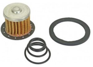
But IF you use one of these paper filters, you need to know that the rust, dirt, etc. is trapped INSIDE the paper element, not on the outside of it like you’d think. Therefore, you can be collecting a lot of junk inside the filter, plugging up the filter element on the inside, and not even know it. One day, you lose all your power and the engine really acts like it is starving for fuel. You thought you would see the rust and dirt collect on the outside of the filter… but you don’t. Surprise! (I hate surprises!)
So, if you are going to use these pleated paper filters, get into the habit of replacing them regularly, maybe once a year, since you can’t see how dirty they are inside. And carry a spare filter and gasket with you in the car. It’s a pretty easy thing to swap out in a parking lot. Kind of messy, but it can be done without tools. Use some disposable gloves and you won’t smell like gas for the rest of the day.
That’s all for now. Keep driving, help each other out, and Have a Model A Day!
Jim
Jim Cannon (MAFCA), Western Model A News June 2021
Top of page
Carburettor Float Level Setting
Use a glass jar with a 3-inch diameter mouth. Mark a line on the outside of the jar 5/8-inch down from the lip. For a fuel fill line, cut a section of old fuel line to length. The funnel is an applicator nozzle that comes with a tube of gasket maker like Pematex. Before cutting the nozzle, stick the fuel line in from the big open end and cut the nozzle about an 1/8-inch longer. Then fit the nozzle on the fuel line to serve as a tiny funnel. This should give a funnel that won’t leak.
While I pour most of the gas directly into the jar, you have to do the final fill using the fuel line/funnel so the float shuts off the fill line.
I find this a lot easier than having to assemble the carburetor and put it on the car to use one of float level gauges sold by Model A supply houses. Especially when it takes multiple tries to get the float level just right.
Eric Shogren, Shade Tree A’s, Western Model A News, Dec 2021
Top of page
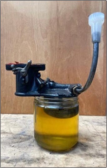
Shut-Off Valve
Easy removal or installation of Model A fuel shutoff valve from Model A gas tanks can be accomplished by procuring a 5/8 x 14 thread nut (NF) and hand tightening it on the outlet of the valve. This gives a surface on which to use a wrench without damaging the threads.
Dexter L. Blether, Longview, Texase, via MAFCA On The Road via Ford Torque and Western Model A News, Feb 2022
Top of page
Stopping at Idle / Throttle Plates
“It Stalls at a Stop”
This is a common complaint often heard from Model A owners. My experience has been that it has to do with the Zenith carburettor. On most forums numerous theories are offered; many of them contradictory.
Every once in a while, I encounter a Zenith that defies being fixed so that it does not stall at a stop. It can be very frustrating. However, I think I may have hit upon the problem.
I recall attending a Zenith seminar years ago at a MAFCA meet conducted by Herman Reise, who was an old fellow, since passed away, who knew quite a bit about Zenith carburettor restoration. He made a statement that stuck in my mind. He said that “there hasn’t been a decent throttle plate produced in 50 years”. Unfortunately he did not elaborate.
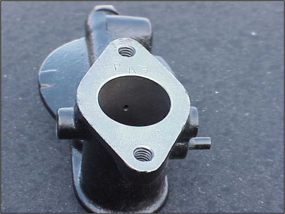
Occasionally I find a throttle plate where someone has filed a groove in it right where it approaches the hole in the throat of the carburettor for the idle circuit. I have never figured out why this is done. I think that doing this would upset the flow of the proper amount of air to the idle circuit.
Snyder’s Model A catalogue has an interesting statement concerning the reproduction throttle plate they offer. “Made of brass as original with correct angles on the edges. USA”. Recently I was rebuilding two Zeniths that road tested perfectly until I came to a stop, then the engine stalled.
Nothing I did to the Zeniths resolved the problem. The float level was set to different heights a number of times, the throttle shaft was replaced, the throttle bosses re-bushed, the float replaced. The float valve was replaced with a Viton tip. Flow tested jets installed. All the passage-ways were open. It was then I began to think about the throttle plate itself. If the throttle plate does not close on the idle circuit hole in the throat properly, it could adversely affect the flow of air to the idle circuit and the transfer from run to idle would be disrupted. Maybe old Herman was on to something. Maybe back in the J.C. Whitney days, the Model A Kingdom was flooded with throttle plates with the angles not ground correctly – that has continued to the present day. I ordered two throttle plates from Snyder and installed them in the two Zeniths that both stalled when coming to a stop. Problem resolved!
This was quite a revelation. It could be that there is a multitude of incorrectly ground throttle plates floating around, or it could be that some of the originals that have survived have become worn such that they do not close on the idle hole properly.
Whatever is the case, when rebuilding a Zenith I will be installing new throttle plates from Snyder. I suspect some of the other better suppliers, such as Bratton’s, are offering the same throttle plate. However they don’t say so in their catalogue.
The small hole in the throat of the upper casting allows air to flow into the idle circuit when the throttle is closed. The throttle plate closes such that half of the hole just peeks above the closed throttle plate.
Tom Endy (Model A FlyerJune 2023) as appeared in Western Model A News, July 2023
Top of page
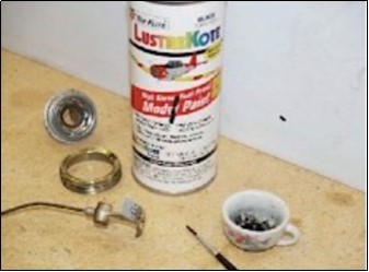
Fuel Gauge Restoration
After spending over 80 years inside the gas tank of my 1930 standard coupe, the fuel indicator was looking pretty sad. Paint was missing from the numbers and the overall appearance was dingy and tarnished. I decided to see if I could bring it back to life.
Since the numbers are actually stamped into the indicator, lower than the surrounding surface, I figured I might be able to flow some new paint into the recesses, wait until it dried, and try to rub the paint off the top surface, leaving just the numbers painted. It worked like a champ. Here’s what I did:
I gathered up a small artist’s brush, a tiny cup, and some fuel proof paint. This is the same model airplane paint recommended to repaint your carburettor. After shaking the paint up for at least a full minute, I squirted some into the small cup.
Getting just a bit of paint on the tip of the brush, I let the paint flow into the recesses of the numbers where they had been chipped or eaten away over the years.
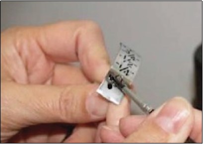
Once the paint had thoroughly dried, I looked around for something to rub the surface with. I decided against a cloth as being too floppy and might actually pull the paint back out of the recesses. I needed something smooth but stiff. A scrap piece of pine, from another project, laying on my work bench caught my eye. A sort of burnishing tool. Perfect!
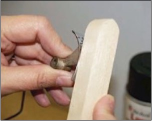
I rubbed it over the now dried paint and it not only took off the unwanted paint around the numbers but it had a sort of polishing effect on the metal as well.
Whatever the surface of the indicator is plated with, it came right back, shiny as new and the numbers looked terrific (the lovely hands belong to my wife. I’m manning the camera.)
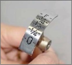
This is going to look great, even behind the old, original bezel.
After cleaning and polishing the inner and outer rings as best I could, my gas gauge is ready to be reinstalled in the fuel tank and give another 80 plus years of service.
Brian Amato, Kwestinq@aol.com, Membership Number 53732, Traverse City, Michigan – as appeared in Western Model A News, Nov 2023
Top of page
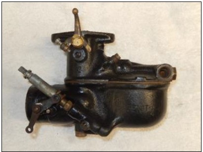
Simplified Zenith Carburettor
There are many articles on restoration of the Zenith carburettor as used on the Model A, and like the rest of the car, its ’beauty lies in its simplicity’. In order to better understand it myself, I have, with the help of those articles and a bit of compressed air, put together some photos and drawings showing the path taken by the petrol, and fuel mixture through the carburettor.
A later carburettor may have an air vent hole high on the side of the bowl above the main jet delivery hole.
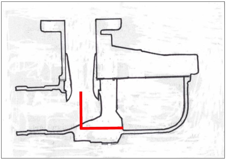
From the fuel bowl, there is a direct path to the main jet, although in reality the drillings do go around corners. The top of the main jet should be in line with the narrowest part of the venturi where incoming air is travelling the fastest.
Fuel level in the bowl is critical and needs to be just below the level of the top of the main jet.
Too high will cause fuel leaks and a rich mixture. Too low will starve the engine of fuel at higher speeds and cause a lean mixture.
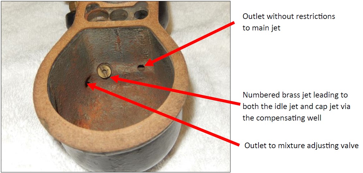
The compensating well
From the brass numbered compensating jet in the bowl, fuel passes through a drilled passage to the compensating well then another passage to the cap jet. The compensating jet allows a small amount of fuel to always be available at the cap jet and idle jet.
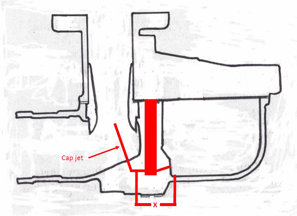
The mixture adjusting valve X is in a parallel path of drilled passages from the fuel bowl, around the compensating well to the cap jet. This allows the driver to deliver extra fuel to the engine if needed.
The Fuel Flow at Idle
The idle jet sits inside a brass secondary well, which is screwed into the compensating well. Fuel reaches the secondary well through two small holes at the lower sides, then travels up through the idling jet and out a very fine hole at its tip. Air from an opening shown below mixes with the fuel at the idle air adjusting screw. The mixture is then drawn into the carburettor throat and engine, at a hole just above the throttle butterfly in the closed position.
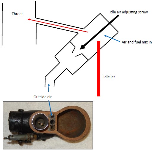
What can go wrong?
If there are no air leaks and the float level is correct, then all that can happen is a blocked jet or things falling apart. The idle jet is very prone to blockages caused by rust or other contamination in the fuel tank. All Jets can be flow tested and soldered up then re-drilled the correct size.
Rob Brown, North Island Model A Ford Club (New Zealand)- as appeared in Western Model A News, March 2024
Top of page