Steering
Front-End Shimmy
Front-end Excessive Play
King Pins
King Pin Bushes
Light Switch Spider Installation
Steering Arm Ball Replacement
Steering Box Lubricant Leaks
Steering Box Servicing
Wheel Alignment
Wheel Alignment
The specification for the toe-in for Model A front wheels is only 1/16 inch plus or minus 1/32 inch. The following method provides a simple and quick way of checking wheel alignment.
Jack up the front axle so that the wheels can just rotate. At a convenient place on the outer surface of the tyres at the front, mark the surface with soft white chalk in line with the wheels at three positions around the circumference to provide average readings. If the wheels rotate true then you may only need one position.
With a metal scribe mark a thin line in the chalk, in line with the wheel for, say, one inch and also mark a line at right angles to provide a positive reference point. Position the reference points on the tyres at a height approximately the same as the centre of the wheel. Measure the horizontal distance between the two wheels using the marks and a tape measure. Rotate the wheels to position the marks at the rear and ideally at the same height, taking into account the radius arm and engine sump, as some compromise may be required. The difference in the readings provides the amount of toe-in (or out). Repeat at the other positions if necessary.
John Morehead, Western Model A News Aug 2012
Top of page
King Pins
After servicing and adjusting front wheel bearings, the bearings are checked for excessive play by holding the wheels and assessing side ways movement. If the play seems excessive then the following checks should be carried out before readjusting the assembled wheel bearings.
Firstly, using a punch or drift tap the head of the locking bolt that secures the spindle (king pin) i.e. from the front of the vehicle. Then on the back of the bolt use a ring spanner to tighten the bolt nut. If this procedure has not been carried for some time, you may find that the nut can be tightened.
Next, jam a large screw driver or similar between the spindle housing and the front axle to ensure that it is a tight fit. Now check the wheel bearing for movement. If the amount of movement has decreased or eliminated, then the problem is in the spindle (king pin) within the bushes or the eye of the axle and not in the wheel bearing adjustment.
John Moorehead, Western Model A News Nov 2014
Top of page
King Pin Bushes
When replacing king pin bushes. you often find one new bush will not be tight in the stub axle (spindle) and it needs to be tight so you can ream it.
I take the bush out again and melt soft solder over the outside of the bush. It needs to be over most of the outside but avoid getting solder too close to one end so that you still have a leading edge to get it started. After soldering, dress off the high lumps. Large high solder lumps makes it too difficult to press in although some of the solder will be pared-off as you press it into the spindle (stub axle).
When pressing in the bushes don’t forget to line up the bush hole with the grease nipples!
Use a bush driving tool and your vice to push them in or out so you don’t damage or distort the bush.
Alan Jeffree, Western Model A News Oct 2012
Top of page
Front-End Shimmy
If your Model a develops front-end shimmy first check the tie-rod end plugs. The components should be inspected for excessive wear and the end plugs should be tight enough to compress the internal springs some 25% of their free length.
To adjust after removing the split pin tighten the plug to give the spring compression required. A large flat blade screw driver can be used. A simple adjusting tool can be made from a piece of flat bar 5 inches long by 1 inch wide and 1/8 inch thick. Bend one end at 90 degrees for approximately ½ inch. This end can then be inserted into the slot in the end plug.
After this work it is advisable to check the front wheel toe-in which should be approximately 1/16 inch.
John Moorehead
A second cause of shimmy can be a sloppy front radius rod ball attached to your gearbox housing. If you have a rubber radius ball (A-3445), over time it softens with oil and the ball can move around causing shimmy. One or two Radius ball washers (A-3440-W) can be used instead of the rubber to keep it all tight. I make my own cupped washers by finding a large flat washer and cup it using a large and small socket all pressed together in an engineer’s vice. You may need to tighten it a few times over a few months as it shapes itself to the ball. When I do this modification I use kit (A-3440-RE) which doesn’t have the springs and sleeves as the original kit.
Alan Jeffree
Western Model A News Dec 2013
Top of page
Front-end Excessive Play
Whilst it is relatively easy to detect play or movement in the front wheel bearings and king pin bushes in the front axles, one location that can be overlooked is wear in the top and bottom of the eye of the front axle. The locking bolt that secures the king pin in the front axle must be kept dead tight to prevent wear in the extremities of the eye of the axle.
One technique to reduce or eliminate this play is to fit oversized kingpins. The eye of the axle may need to be carefully reamed to result in a tight fit of the oversized pin. The king pin bushes in the axle will then have to be reamed to achieve a firm sliding fit between the king pin and the bush. New locking bolts should be installed.
There were three styles of locking bolts used from the start of production up to mid 1929 and the Style No. 3, which is a cotter pin type with a single large nut, was used until the end of production.
Also the securing nut should be positioned to the rear as it acts as a stop.
Some years ago the writer used this technique on our Model A front end and this source of play or movement was eliminated.
The Model A Ford Club of South Australia provides oversized king pins on an exchange basis. In the past the oversize pins were approx 0.008 inch oversize. For current availability, details and price contact:
Model A Ford Club of SA, PO Box 202, North Adelaide, 5006 or visit their web site
Western Model A News, Western Model A News June 2017
Top of page
Steering Box Lubricant Leaks
Like many Model A’s, our phaeton suffered from lubricant leaking from the steering box even though the bushes are in good condition. Whilst the amount of lubricant over a period of weeks only amounted to a few drops – it was annoying.
A fellow club member, (John Forbes) advised that he had solved the problem with new bushes and a spring loaded felt washer positioned adjacent to the frame. I tried the felt washer with limited success.
Whilst lying on my back studying this problem, it was noted that approx. 1/8″ of round shaft protruded from the steering box through the frame before the square section. I removed the two securing bolts holding the steering box to the frame and applied gasket sealant between the steering box and frame. A standard two lip oil seal was placed over the shaft and against the outer side of the frame. Again, some gasket cement was placed between the outer part of the seal and frame. A spring and thrust washer was positioned between the seal and pitman arm (see sketch).
After some months and several hours the steering box remains free of leaks!! Whilst this technique is not as sound as removing the steering box and machining the box to take a special seal, for just a few dollars my problem was solved!!
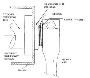
John Moorehead, Western Model A News Feb 2002 (re-printed Western Model A News, May 2021)
Steering Arm Ball Replacement
Like all mechanical things, the moving parts of a steering system are subject to wear. Eventually the wear will start you wondering: “ls this car safe to keep driving?”. lf you are asking yourself that question, it’s about time the system was repaired.
When I restored my car, I replaced the steering sector shaft and bushes. The steering balls, although slightly worn, were serviceable. The steering worm had minimal wear and anyway, I couldn’t get a new one at the time.
The steering, while not perfect, was quite acceptable. However, over the years, free play in the steering wheel had increased to 150 to 200 mm. Obviously a complete steering system overhaul was necessary.
The first things inspected were the steering arm balls. All these were badly worn with replacement being the only option. There is more than one way this can be done, so will discuss a couple of the more common methods.
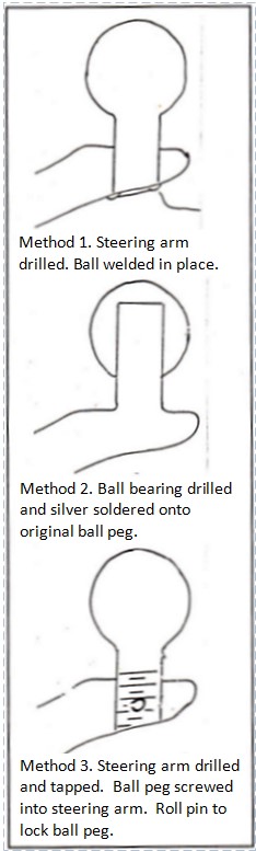
Replacement balls are available that require the old balls to be cut off, the arm drilled and new balls are then fitted and welded into place. I have some reservations about welding steering parts. It is generally considered an unacceptable practice to weld any steering parts. The high localised heat created during the process can cause local heat stress that may result in fracture and failure.
An ‘A’ grade welder should be able to minimise local stress by correct selection of welding rods and appropriate pre-heating. However, there is still the problem of maintaining or re-establishing the correct degree of hardness and, given that the material used in old vehicles while probably of good quality, is an unknown quantity. Even an ‘A’ grade welder may have difficulty selecting the appropriate rod. This method must remain the least preferred.
An alternative is the method developed and used by John Broadbent of Victoria (c1992). John’s method involves machining the worn ball to a parallel peg. A steel ball bearing of the appropriate size is softened and drilled to fit the peg. Once drilled, the ball is re-hardened and silver soldered into place. The heat used for silver soldering is much more general and nowhere near as intense as arc welding, so the possibility of internal stress is greatly reduced. I am not sure what John does to stop the heat from silver soldering effecting the hardening of the ball and steering arm, I trust he has this under control.
A third method, which would be the preferred method if you can organise it, is to cut and drill the steering arm in much the same way as the first method described. Instead of welding the new ball into place, screw it in using a fine thread (UNF). Fit the new ball, then drill through the arm and ball peg to fit a roll pin is a locking device. Once all the machining and drilling is completed, send the ball away for heat treating. The completed ball can then be refitted to the steering arm and locked into place with the roll pin.
The big advantage of this method is that the arm is not heated in any way, and once treated, the ball is not heated again.
It is important to remember that heat is used to give metal many of its characteristics of strength and hardness, so any heat applied after initial treatment can effect those characteristics.
I sent my steering arm to John Broadbent for re-balling and the result looks good. I can guess only time will tell. John told me he has been using this method lor about five years at that time and, so far, has had no problems.
Ray Mahony, Western Model A News April & May 1992
Steering Box Servicing
The Model A Ford has three different steering boxes:
1. Two-tooth sector, used in 1928 and some early 1929 models.
2. Seven-tooth sector used in 1929 models. Both the above are non-adjustable with respect to gear tooth backlash.
3. ln 1930 a fully-adjustable steering box was introduced.
The advantage of the seven tooth sector is that, as you move towards a lock, a more constant tooth contact (and therefore a more constant backlash) is maintained. With only two teeth, as the sector starts to move away from the straight ahead position, the teeth begin to move out of mesh. This increases the backlash.
The steering box in my vehicle, being a late 1929 model, has a seven-tooth sector, therefore the following applies specifically to that model. There is, however, very little, if any, difference in overhauling the 1928 and 1929 model steering boxes. Therefore the following is applicable to both.
The steering worm and sector teeth in my steering box showed no appreciable wear. I am lead to believe that the majority of steering worms and sectors are quite serviceable and do not require replacement. Approximately 0.004″ wear was evident on the sector shaft and the bushes were considerably worn. The steering lower bearing surface and bush were also badly worn. Both main shaft thrust bearings were rough and required replacement.
Needle roller bearings were chosen to replace the sector shaft bushes. The steering box housing needs to be machined to fit the bearings. A slightly tighter fit than normal is recommended because the bearings are in fact a little big for the shaft. A tight fit in the housing will close the bearing down on the shaft. I also fitted a neoprene seal to the housing. The seal chosen has two lips; one to keep the oil/grease in and one to keep dirt out. The bearing used was one listed in the “East Coast” or “Snyders” catalogue, although purchased locally.
Some people make an eccentric main shaft lower bush, which moves the worm sideways and closer into mesh with the sector. Although I believe this to be very successful, I chose to use needle rollers. The roller bearing selected has an outside diameter that is as close a fit as you will get the steering box end and bush housing but the main shaft needs to be turned down to 0.650″, or a fraction less to allow for a slightly tight fit of the bush in the housing.
Assembly and Set-up
- Fit all bearings and the seal to their housings and lubricate well.
- Fit the worm shaft thrust bearings; one above the worm and one below. Fit the shaft with worm and bearings to the steering box.
- Fit the worm shaft and bush housing. Brass shims fit between the bush housing and the steering box housing to adjust the main shaft end float. The shim stack should be adjusted to remove all end float from the shaft but should not put any pre-load on the thrust bearing.
- I used a nylon washer in the end housing to rest against the end of the main shaft and act as a seal. I don’t think it was very successful, so you might be able to think of something better.
- Assemble the rest of the steering box; fit the steering sector shaft with its thrust washer. Fit the steering box cover and gasket.
- Adjust the sector shalt adjusting screw (located on the cover) to remove all end play from the sector shaft. Do not put any load on the shaft.
- Check the backlash by measuring free play at the steering wheel. Up to 50mm is acceptable. lf you wish to adjust the backlash, it can be done by reducing the thickness of the sector shaft thrust washer on a surface grinder. How much must be removed from the washer is a matter of trial and error but remember, if you take too much off, you can’t put it back again.
By doing what I have just outlined, I reduced the free movement at the steering wheel to about 50mm. This would have been less if I had fitted the sector shaft bearings a bit tighter (we learn with every job we do), still the car handles much better, feels safer, is lighter to steer and even has some self-centering after a corner – and it never had that before.
Unfortunately I have lost the receipt for those bearings, so cannot quote part numbers lor the bearing or seal. However, if you take some steering box parts with you when you get the bearings you will have no problems.
Ray Mahony, Western Model A News April & May 1992
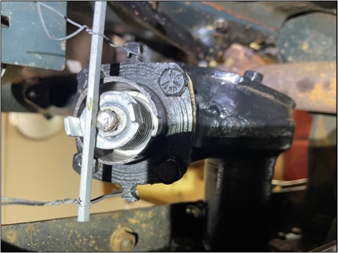
Light Switch Spider Installation
There are several tools and techniques around to help get the circlip installed in the light switch spider on the end of the horn rod. I have found the following method easy, leaves plenty of access to get the circlip in and leaves both hands free to do so. I use an Allen key as I can always find one and they are very stiff for their diameter.
Ian Steer, Western Model A News Dec 2023