
Wheels and Brakes
Wheel Alignment and Balancing
Brakes Description & Adjustment
Brake Adjustment
Brake Equaliser
Brake Spring Installation
Cast Iron Brake Drum Info
Early Brake Cross-Shafts
Front Wheel Bearings
Handbrake Rattle
Rear Brake Cam Shaft Alert
Rear Hub Removal
Tyre Mounting
Wheel Alignment and Balancing
The brief summary of this tip is that Model A wheels can be aligned and balanced by the machinery in modern tyre shops – and fantastic results achieved.
Paul Kelly, Western Model A News, November 2025
Top of page
Front Wheel Bearings
Front Wheel Bearing Installation & Adjustment
- See that front hub, inner and outer bearings are packed with grease
- Front hub washer should slide over threads on spindle body with fingers (loose fit)
- Install nut and tighten it while slowly turning the brake drum so that all component parts are pulled together snugly; that is, inner and outer bearings will be snug in cones, washer is tight against outer roller bearing, and nut is tight against the washer. (There will be a slight drag when drum is turned.) Not over 8-10 ft-lbs of torque is required to get these results.
- Turn nut BACK two castle slots (this is approximately 1/4 turn of nut); insert cotter pin and try bearings for a slight side play and a free spinning drum or wheel.
Don’t forget the cotter pin! The nut will back out and the wheel will come off. That will totally spoil your Model A Day!
Western Model A News, January 2020, courtesy of Jim’s Tech Tip, Jim Cannon of MAFCA
Top of page
Early Brake Cross-Shafts
SECRET FORD MODEL A RECALL
It is now common practice for vehicle manufacturers to issue public recalls to rectify manufacturing faults. In the time of the Ford Model A manufacture, this was not common practice. In 1928 it was a different world when the individual was ultimately responsible for looking after himself.
The initial Model A brake mechanism was designed to apply equal pressure on all four brake rods through a complex system of equaliser lever and sliding pivots on the two cross shafts. Two stops were formed from the frame cross member and assisted the adjustment procedure (Refer Jan.1928 Ford Service Bulletin). To simplify adjustment, Ford replaced the adjustable brake rods with nonadjustable rods possibly as early as April 1928. In June 1928, the Service Bulletins commented that the stops in the back flange of the centre cross member were now eliminated.
In correspondence to the Ford Dealers reference was made to the installation of a “mystery” part on cars which were manufactured without the brake shaft stops. This involved vehicles manufactured from approximately mid April 1928 to September 1928, i.e. some 250,000 cars. It was found that these stops prevented any possibility of the brake equaliser coming out of the brake operating shaft. This implies that in some cars the brake system had fallen apart!!
The dealers/service outlets were instructed to install part No, A-2476 on the frame cross member to form the stops that had been removed. Further more it was deemed not necessary to bring this modification to the attention of the owner. To the best of the writers knowledge, part No. A- 2476 was not listed in any Ford Parts Price List.
In November 1928 Ford reported that the complicated equaliser cross shaft assembly had been replaced with a single one piece cross shaft.
If you have a 1928 Model A with the original brake assembly, check that the cross member has the stops, i.e. the original stops formed in the cross member or the retro fitted part, (A-2476)
John Moorehead, Western Model A News, Jan 2017
Top of page
Cast Iron Brake Drum Info
This information is about reproduction cast iron brake drums. Grey cast iron is what most manufacturers use to produce cast iron parts. It has been in use since the Model T’s and Model A’s came into existence. Even the reproduction cast iron drums made in China are grey cast iron. Some cast iron drums are advertised as nodular iron. Nodular iron is grey cast iron which has small amounts of magnesium added to form a premium cast iron. Nodular iron is also known as spheroidal or ductile iron. It has excellent ductility, higher tensile strength, and better corrosion resistance than grey cast iron.
Ductility refers to the ability of metal to stretch, bend, or twist without breaking or cracking. Tensile strength is the property in metal which resists forces acting to pull the metal apart. Corrosion is the wasting away of metals by slow gradual combination with other elements and chemical compounds.
You may use this information to make an informed decision before purchasing your new reproduction cast iron brake drums!
Lynn Sondenaa, Volcano A’s, Western Model A News,, September 2020
Top of page
Brakes Description & Adjustment
The following article is taken from a Brake Re-liner’s Manual put out for international correspondence schools, published in 1933. This publication was purchased by my father, Norm Jeffree who was doing his apprenticeship at the time. The book mentions 127 different makes of cars and trucks. Several with hydraulic brakes and some with booster assistance. I will mention a few to show the variety of vehicles covered—Acorn truck, Duesenberg, Gardner, Jewett, Page etc, etc.

EARLY FORD MODEL A
Early Ford Model A cars are equipped with four internal brakes, which can be operated by either the foot pedal or the hand brake.
Service Adjustments
With car on jacks release hand lever to full release position. Tighten nut 1, Fig.4, for front and 2 for rear, until brake drags, then back off until wheel is just free, being sure to back off the same amount for each wheel. If linkage has not been disturbed, the rear brakes should just begin to hold when pedal is down one inch. With one and one half inch pedal depression the front brakes should begin to hold and rear almost lock. Two inch depression should lock rear and hold hard on front but not lock. If suitable adjustment cannot be obtained by wheel adjustment at 1 and 2, Fig 4, check the linkage.
Major Adjustment
All lever joints should be properly lubricated and wheel bearings tight. Disconnect rods 3, 4, 5,and 6 at the equalizer shaft. Levers 7 and 8 should be against stops 9 and the shafts at each side should be in the center of brackets 10. Unless the shafts 11 are bent, the levers 12 should be vertical. With levers 12 vertical and levers 7 and 8 against stops 9, adjust rods 3, 4, 5, and 6, just taking up free travel of the brake levers 13 and 14. Adjust brakes as for minor adjustment. This article has been copied direct from the Manual.
If you fit a floater motor to your Model A, you SHOULD replace shafts 11 with a one piece shaft. This is another story, as the original one piece doesn’t have a hand brake attachment!
LATER FORD MODEL A
Ford cars produced after the summer of 1928 are equipped with six internal brakes, one on each front wheel and two on each rear. The service brake operates on all four wheels, while the hand brake operates independently of the service brake on the rear wheels only. About the time of adding the separate hand brake, a new type of cross shaft was introduced which, however, is interchangeable with the two-piece shafts used on the earlier cars. The pull rods were also changed, the earlier adjustable rods being replaced by rods which are non-adjustable. The linkage layout is now as shown in Fig 5. The construction and adjustment of the service brakes remains the same as on the earlier models mentioned in the previous newsletter.
Major adjustment

Make sure that all levers and joints are properly lubricated. With the car on jacks, disconnect front and rear pull rods 2 and 3, Fig 5 at the wheel ends. Disconnect pedal rod 4. If the car is equipped with a multi disc clutch, adjust the length of rod 4 so that when the end of rod touches the cross member of frame, the brake pedal will clear underside of floor board by 1/2 to 3/4 inches. Then connect rod 4. If the car has a plate clutch, pull the brake pedal against its stop and adjust rod 4 until there is 1/16th inch clearance between rear end of rod and rear flange of the cross member. Adjust brakes at wheels as for Early Ford Model A mentioned in January Newsletter. Adjust pull rods 2 and 3 so that when all free movement is removed the rods can be hooked up without disturbing the position of the levers.
The above information was written when Model A’s were current everyday vehicles. We as restorers have probably scrounged baking plates, shoes and rods etc, which may or may not be in top condition. From my experience the pin holes (A-2027) in old shoes let them hang outwards and bind on the inside of the drums, which make it impossible to get a proper adjustment. The backing plate Roller tracks (A2011-A) are scalloped and you don’t get a proper outward push. If you have mixed and matched the Brake adjusting shafts (A-2042) your shoes wont sit in a perfect circle! All of the 1933 information still wont get you the proper stopping we need in today’s traffic unless all of the above has been worked on, and brought back to original standard.
Alan Jeffree, Western Model A News, Feb/March 2014
Top of page
Brake Adjustment
There are numerous articles available in our club library and videos detailing brake adjustment techniques. Also, the use of front brake floaters and other accessories to improve the stopping or slowing power of the Model A are well documented and available from parts suppliers. It is essential that all brake components are in good condition. Also that:
- The brake cross shaft is in the vertical position
- The front actuating arms are positioned some 15 degrees forward with all free play removed
- Adjustments are made with the brakes cold
The initial adjustment method recommended by Ford specified 60% braking on the rear wheels and 40% on the front wheels. With the use of various accessories, it is now generally accepted that adjustment can be made with 60% on the front wheels and 40% on the rear wheels. Why not aim for 50% front and back?
A brake pedal adjusting board is beneficial to make an effective and accurate adjustment (refer to the sketch below). This device is made to suit your Model A. After jacking-up the vehicle, turn the brake adjusters on all 4 wheels until the brakes just start to drag and then back off one or two notches. Always spin the wheels in the direction of forward motion.
Position the pedal adjusting board between the front seat and pedal reference line. Then depress the pedal to the first notch (one inch). Turn the adjusting wedges on the front wheels until the brakes just begin to hold. Move the pedal to the second position and adjust the wedges on the back wheels until the brakes begin to hold. Move the pedal to position three (depressed to the two inch mark). The front brakes should be locked and the rear brakes should have very heavy drag. Obviously some checking and adjustments are needed and road testing may require some fine tuning of the brake adjusting wedges to ensure braking in a straight line.

John Moorehead, Western Model A News, April 2018
Top of page
Rear Brake Cam Shaft Alert
Reference articles for the maintenance of Model A brakes emphasise the need to keep all
moving parts in good condition to ensure optimum braking. One part that is sometimes overlooked is the rear brake camshaft that operates the brake cam and the movement of the brake shoes. This cam shaft is subject to considerable forces and hence will wear in the bushes.
From the start of production to the end of manufacture, three designs of rear brake cam shaft were used. Up until the mid 1928 (when there was no separate emergency brake), two designs were used. After this period, a longer 3 & 7/8 inch unit was standard manufacture compared to the initial 2 & 7/8 inch designs.
If the early Model A rear brake cam is to be replaced, check the design before ordering
replacement parts.
John Moorehead, Western Model A News, Aug 2017
Top of page
Handbrake Rattle
Some years ago, Member Steve Read gave me a tip on how to stop the Model A hand brake from rattling. I am sure Steve wouldn’t mind me passing it on!
Remove the hand brake lever from the vehicle and dismantle it. This will all take some time but it is better than driving your Model A with your foot resting on the lever all day!!
You have to remove the button on a 29/31 or the squeeze handle on 28s. Find a piece of rubber or plastic tube which just fits over the thin wire rod which travels down the inside of the chromed outer. Make it as long as possible, making sure it doesn’t interfere with the action of the mechanism when together.
Reassemble the chromed lever etc and reinstall into the vehicle.
Before starting this process with 1928 lever type handbrakes, check that it isn’t the actual squeeze piece that is rattling. If it is, you need to tighten the rivet which it pivots on. Careful not to tighten it too much or the lever may not move freely enough to work!
Alan Jeffree, Western Model A News, Nov 2012
Top of page
Rear Hub Removal
The rear hubs and drums are bolted onto the tapered axle shafts quite tightly. It is not always easy to get them off when you need to inspect the brakes or check the rear wheel bearings. Don’t let this put you off.
You can buy a special “hub puller” that is designed to help get the hub off of the axle. It uses a large bolt that you screw in to press against the axle, and the puller pulls on the hub.
Some Model A hubs were made with a ridge that sticks up, away from the hub body. The puller connects with that ridge. Other hubs were made with a groove machined down into the hub. The puller goes down into that groove and pulls as you tighten the bolt.
Some pullers are specific to the style hub you have (ridge up or groove down) so before getting a tool, you should remove a wheel to see what kind of hub you have to be sure to get the right puller. Other pullers are designed to work with either style hub, which is handy––so you might want to look for one of them.
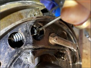
When using the puller, it is hard to keep the drum from turning as you tighten the bolt on the puller. Put a wheel lug nut on the drum temporarily and put a 13/16” box-end wrench on it. Press down on that wrench while you lift up on (tighten) the big bolt in the puller. The wrench will jam against the hub and stop the drum from turning as you tighten the bolt.
When using the puller, tighten the big bolt, then tap the head of the bolt with a hammer. Tighten the bolt again, then tap with a hammer again. Repeat this until the hub pops free of the tapered axle.
Removing the rear drum is a pretty common task for servicing a Model A, so it is worth investing in a hub puller tool. It makes the job easier and helps you get back on the road quickly too.
Have a Model A Day!
Jim
Jim Cannon, MAFCA
Top of page
Brake Spring Installation
Do you have trouble installing the newer, stiffer rear brake springs – especially with the emergency brake backing plate installed ? I certainly did (and was reminded of this when I found only one new spring, and 3 old springs when I had my rear brakes apart recently. Last time, I had obviously decided after the first new spring that it was way too hard, and re-installed the 3 other old springs).
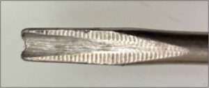
However, by sacrificing a 4mm flat blade screwdriver, I have made a tool that makes it a piece of cake.
First, grind and/or file a groove on the end of the screwdriver.
Next, snip a bit of the return off one end of the spring.
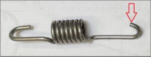
Then slip the clipped end of the spring on the shaft of the screwdriver, rest the grooved end of the screwdriver on the pin and straighten the screwdriver up. The end of the spring will slide down towards the pin. Use a second screwdriver to push it the final distance over the end of the pin.
Ian Steer, Western Model A News, Apr 2022
Top of page
Tyre Mounting
Mounting a new set of tyres can sometimes be difficult for Model A owners as it is not normally something you want to have done at the tyre store. Modern day tyre stores will likely damage the paint and the hubcap on a Model A wheel while using their tyre mounting apparatus. In most cases installing new tyres is a do-it-yourself task.
To make the job easier, I built a simple mounting board to place the wheel on while pushing the new tyre on.
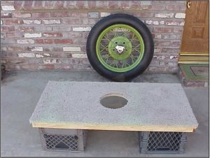
The board is made of ¾” plywood 44” long and 21” wide. There is a border 1½” wide nailed around the bottom edge. Two plastic “milk carton” containers fit nicely under the board and will easily support my weight along with the wheel and tyre. A 9” hole is cut in the centre and the surface is covered with carpeting.
The wheel is placed on the board with the hubcap facing down into the 9” hole. To make the tyre slide on the rim easy, obtain a large can of baby powder. Liberally sprinkle the powder on the inside of the tyre and especially around the bead. Coat the inner tube with powder as well. It is easy enough to put the tyre on the rim, but the hard part is to get the bead all the way around the rim once the inner tube has been installed. This is done with the heel of my foot. I stand up on the tyre and work the bead into place with my heel.
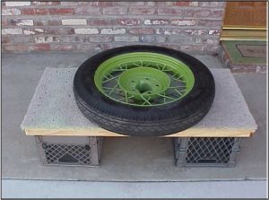
To keep from losing my balance and falling off the board I mounted a handle up under the eves of the house to grasp onto. The handle makes it easy to maintain balance while walking the tyre onto the rim. It is also a handy place to hang newly painted parts to dry.

Tom Endy, Santa Anita A’s, via Western Model A News, Apr 2023
Top of page
Brake Equaliser
The brakes on a Model A are adequate if properly adjusted and maintained correctly. I remember reading that Henry Ford wanted “metal between the pedal and the road”. For him, four wheel brakes were a huge leap forward from just having rear brakes on the Model T. He wanted 60% braking on the rear and 40% on the front to, as he put it, stop the front wheels from skidding and losing steering control.
There are so many joints and pins that become worn in the braking system that trying to achieve equal braking on each wheel is difficult. The best way to achieve this is use the brake adjusting method developed by Club Legend, Steve Read.
- Put the car up on 4 stands.
- Adjust all 4 wheels so they are locked up.
- Check front brake levers are 15 degrees forward, brake cross shaft is vertical, adjust the brake rods lengths until they are a “thumb push fit” in the clevis.
- Back off all 4 brake adjusters one or two clicks.
- Road test and adjust if necessary if pulling to one side.
This method works well because it compensates for all the wear in all the components.
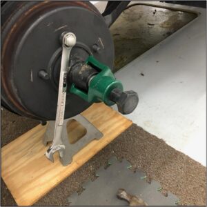
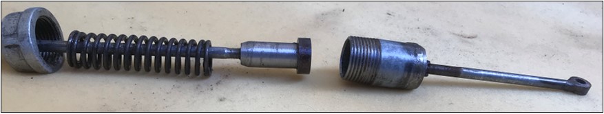
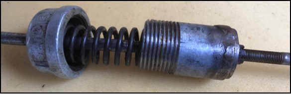
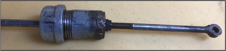
The AR Model had the 3 piece brake shaft to apply even pressure to both sides. That got me thinking about how I could achieve even braking pressure on the front wheels without locking them up into a skid. The rear brakes on a Model A are self energising during braking. A modern addition of brake floaters to the front makes sure there is even pressure on the shoes. To get even pressure on the brake rods for the front, I made two compressed spring devices (see photos) that can be adjusted to allow the brake rod to “stretch” by compressing an enclosed heavy spring (3-4mm only). This ensures that even pressure is applied to both of the front brake levers. I have tested these on my “near concourse 1928 Ute” over the last couple of years and am still pleased with the improvement to its braking.
Materials: 1”pipe and 1”cap from the big green shed, scrap steel turned and threaded on the lathe and most importantly a Model A valve spring inside each. The threaded end of the short brake rod and locknut is used to adjust the travel of the spring to only 3-4mm.
The engineering is rustic, it’s not pretty, but it works!
Horace Misko, Western Model A News, Sept 2023
Top of page